SIMulation Workbench Tests
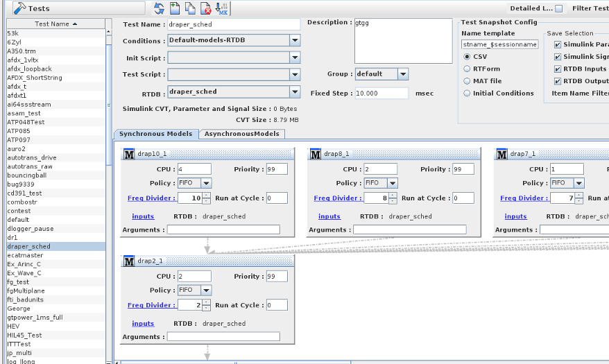
Creates and configure simulation tests. Although initial conditions and test sessions are properly a part of a test’s configuration, these aspects of a test are dealt with in their own forms. See Initial Conditions... and Test Sessions....
Once a test is created and saved to the real-time host, most settings cannot be changed: only the settings on the individual models and the condition sets (including selecting the default one) can be changed on a saved test. This prevents invalidating archived log files. To run a variation of a test, use the Copy button to create an editable copy.
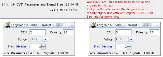
Note: For tests that include Simulink™ models, the space requirement in the CVT shared memory is shown. The space includes the memory needed
for the Simulink parameters, signals as well as the RTDB CVT size. The total space available in the CVT is also shown. If the total CVT size is lower that the space
required to run the specific test, the test will not be able to run and one or more models may crash.
The size of the global CVT can be increased by editing the SimWB starting script cfgsrv.sh in /usr/local/ccursim/bin/ changing the line where cfgsrv is started
to add the command line parameter -S XXXX where XXXX is the maximum number of double (including arrays) that the CVT can contain. The default size is 1000000.
Replace the line
$SIMWB_ROOT/bin/cfgsrv
   with
$SIMWB_ROOT/bin/cfgsrv  -S XXXX
Save the file and restart SimWB with service simwb restart.
|
When the global CVT is too small, the message highlighted in red will show.
|
Button Bar Controls
Detailed List

Replaces the simple list of tests on the left side of the form with a detailed list of tests at the top of the form:
Filter Tests
Displays in the test lists only tests whose name matches the regular expression. See Regular Expressions.
Demonstrate 
Opens a short video clip that demonstrates the basic workflow of this form.
Help 
Opens this section of the manual.
Delete
Deletes the selected test.
Copy
Creates a copy of the selected test. Since saved tests cannot be edited, the alternative is to create a copy of the saved test and make the desired changes to the copy. The copy will be assigned a unique name based on the original test’s name. Until the test is saved to the real-time host, the name and other settings can be edited.
New
Creates a new test. The new test will be assigned a unique name. Until the test is saved to the real-time host, the name and other settings can be edited.
Force remake of all models
This will force all models to be recompiled and relinked regardless of dependencies.
Current RTDB
Shows the name of the real-time database currently loaded for editing. See New/Select RTDB....
Apply
Commits all pending edits to the real-time host. See Apply .
Cancel
Discards all pending edits.
Test Settings
Test List
Simple list of tests on the left side of the form, or a detailed list of tests at the top of the form, depending on the Detailed List option. Select a test from the list by clicking on it. This will show that test’s settings and enable the editing buttons at the bottom left corner of the form.
Test Name
Name of the selected test. The name of copied and new tests may be edited until they are saved to the real-time host by pressing the Apply button.
Conditions
Default initial conditions set of the selected test. New tests have an initial conditions set called Default-models-RTDB by default. Initial conditions sets may be created and edited in the Initial Conditions form, but only after the test has been saved to the server. The default initial conditions set can be changed on a saved test. See Initial Conditions....
Initialization Script
Optional script that is run as an initialization program before the test starts running in real-time mode.
The initialization script is started by the scheduler after the RTDB has been loaded in memory and the I/O tasks have finished initialization but before the
real-time simulation loop starts executing. The purpose of the initialization script is to setup the sub-systems connected to SimWB via hardware I/O.
The initialization script has access to the I/O through setting/getting values of RTDB items mapped to specific I/O just as the models or the optional synchronous test script.
Once the initialization script terminates execution, the scheduler will proceed and initiates execution of the real-time simulation loop.
The initialization script is written with the same language/syntax/API as a regular test script.
Test Script
Optional script that is run during sub-cycle 2 of the test cycle of the selected test. i
The test script runs synchronously during the real-time simulation loop after the inputs have been processed (sub-cycle 1) and before the model sub-cycle (sub-cycle 3).
The test script can be written in 'C', 'C++', 'swm' or python language.
A test script can be written using the built-in SimWB editor in the SimWB control center.
The script name cannot be changed on a saved test. Create a copy of test with a different script instead. See Scripts... and Test Script.
RTDB
Real-time database used by the selected test. This setting cannot be changed on a saved test. Create a copy of the test with a different RTDB instead. See Mapping I/O Points to Hardware.
Description
Description of the selected test for documentation purposes. This setting cannot be changed on a saved test. Create a copy of the test with a different description instead.
Group
Group that the selected test belongs to. See Group Table.
Fixed Step
Duration of a test cycle of the selected test. This setting can only be set on tests with no Simulink models. Simulink models define the test cycle duration themselves. This setting cannot be changed on a saved test. Create a copy of the test with a different fixed step instead.
The unit in which fixed step is presented and entered is selectable. Click on the units after the field to cycle through microseconds, milliseconds, and seconds. All fields presenting the fixed step value throughout the Control Center will use the same unit and the unit choice is preserved across invocations of the Control Center.
Model Sub Panel (Synchronous Models)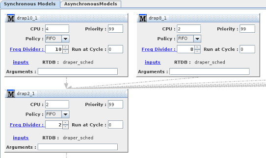
This panel shows the synchronous models that are run during sub-cycle 3 of the test cycle. A block is used to represent the model and show the models’ settings.
Once the test has been created, models cannot be added, removed, replaced, or have their dependencies changed. When you want to alter the test configuration, it is recommended that you
create a copy of the test with different models or different dependencies instead. Settings for the individual models such as priorities and CPU assignment can be changed on a saved test.
The arrows drawn between models indicate dependency. A model must finish running before models it points to may begin running. See Scheduler Period Run.
To add a model, right click in an empty area in the model field and select a model from the context menu that appears.
To remove a model from the test configuration click on the  (close) button in the upper right corner.
To add an execution dependency between two models (I.e to force a model to wait for another model to finish before starting execution) , position the mouse on an empty area in the model’s frame,
then click and drag the mouse from that model’s frame to the frame of a model that depends on the first model and release the mouse button. An arrow will be drawn between the two model’s frames, or erased if there was one already.
Note: In model execution chains, the frequency divider of the Next model must be a multiple of the frequency divider of the Previous model in order to guarantee synchronization. When this alignment is broken,
the arrow indicating the dependency appears dashed and grayed out.
Starting with version 2025-1.0, execution dependencies between models are validated during the configuration process, while pre-existing invalid execution dependencies are indicated by a dashed red arrow.
|
Synchronous models can be created and built using the User Model panel of the SimWB Control Center.
Synchronous models should conform with the following structure of execution:
        int main(int argc, const char *argv[])
        {
            int i;
            /* This will let the scheduler know we are running */
            ccur_init(argv);
            /* Init model exchange if any */
            ccurRTDB_modelDataExchangeInit(argv[1]);

            /* These cycles are for cache warm-up, and are not part of the realtime loop */
            for (i = 0; i < ccurSched_getTaskInitCycles(); i++)
                ccurSched_waitNextFrame();
            while (1) {
                ccurSched_waitNextFrame();
                ccurRTDB_modelCopyInputs();
                /* Do your realtime work in the loop here */
            }

            return(0);
        }
An example model can be created from the SimWB template through the same User Model panel .
Model Sub Panel (Asynchronous Models)
|
This is the panel for asynchronous models. Asynchronous models are initially started by the SimWB scheduler but once started, the models are self scheduling.
Asynchronous models like synchronous ones can also be scheduled in an execution chain where their execution order is determined by how they are linked together.
Once a particular execution chain has finished running, the first model in the chain is restarted.
In order to prevent the execution chain to spin, the first model in the chain must dispatch itself via a timer or some other asynchronous mechanism that will prevent it from spinning.
Asynchronous can be created from a template through the User Model panel in the SimWB Control Center.
All asynchronous models should be structured to run in a loop as :
    while(!exitRequest)  {
       /* When we are first in the execution chain, microSec passed
          into the ccurSched_waitAsyncResume() call  controls
          the wait/resume mechanism:
        With -1 we will pause() inside the routine and then be
          resumed by the thread timer
        With 0 , we return after the execution chain has completed.
        With > 0, the routine will do a usleep(microSec) and then
           returns when the execution is completed.
        When we are not first in the execution chain, the predecessor
            in the chain will resume us when it completes execution and
            the parameter microSec passed into the routine has no effect.
        */
       ccurSched_waitAsyncResume(-1);
       if (exitRequest) {
           break;
       }
       ccurRTDB_modelCopyInputs();
       /* Do your work in the loop after this  */
      } /* end of while */
|
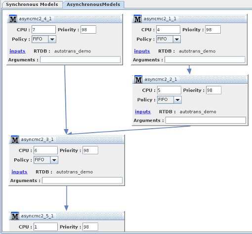 |
Asynchronous models are added to the specific test in a similar fashion to synchronous models. Right clicking on the pane will show a list with the asynchronous models available under
this project.
|
Create an example in the User Model panel interface to see the template code generated for the asynchronous model.
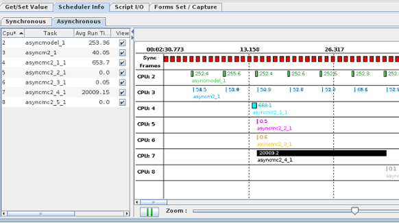
The frame of execution can be viewed in the asynchronous tab of the Scheduler Info tab in the RTViewer.
The display shows how the asynchronous models run with respect to the execution of the SimWB synchronous loop. The red boxes at the top of display represent the synchronous frames of execution;
a maximum of 1 second of execution is shown. The display can be zoomed in / out with the slider control and can be scrolled in time with the horizontal scroll bar.
The display refresh can also be paused so it is easier to examine the sequence of executions of the multiple asynchronous models.
The rate of execution of the top models in the chain might not be congruent with the synchronous loop causing the display to flicker as the execution of some models move around the 1 second of execution displayed.
|
|
Model Settings
Settings may be made in the frames located in the model region, even if the test is saved to the real-time host. Multirate Simulink models have an additional table to allow setting the CPU on each thread.
CPU
CPU on which the model will run during a test run. This setting can be changed on a saved test. The Real-Time Viewer can change the CPU assignment of a model dynamically while the test is running. See Synchronous Tab.
Priority
Scheduling priority at which that the model will run during a test run. This setting can be changed on a saved test.
Policy
Scheduling policy with which that the model will run during a test run. This setting can be changed on a saved test. See Scheduling Parameters.
- Other :
Non-real-time, interactive scheduling policy.This is the default Linux time slicing policy.
- Round Robin :
Real-time scheduling policy where a process whose time quantum has expired can be preempted by another process of the same priority.
- FIFO :
Real-time scheduling policy where a process can not preempted by another process of the same priority.
Freq Divider/Freq Multiplier
Clicking on the underlined label will toggle between divider and multiplier.
Divider :
Sets the frequency in terms of the test cycle’s duration (Fixed Step) at which the model will be run.
Setting the first number to N will cause the model to only run once every N test cycles.
When running the model at a reduced rate by setting the divider > 1, the model is allowed to run for N frames. It has to rejoin to the output cycle at frame N. Failure to do so would trigger an overrun.
Multiplier : This will run the model N times during the model sub-cycle.
Using a frequency multiplier for a model is equivalent to reducing the fixed step size used by the model.
So a model that needs a smaller step size than the main simulation loop can be run as part of a slower simulation loop.
Obviously, running the model multiple times during a single SimWB model sub-cycle will increase the time required by the model
to complete its computation. On the other hand, the results produced by the model may be totally inaccurate when the fixed step is too large.
Example:
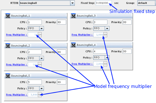
In this example we created a test that runs 5 instances of the same model. Each model run with a different step size. The simulation loop for the test runs at a basic rate of 0.001 sec. This is a simple example of a bouncing ball dropped from a height of 10 m.
The model includes a dampening factor on rebound.
| Model instances | Test definition |
| 1 : step size = 20 μs | == 0.001/50 |
| 2 : step size = 2 μs | == 0.001/500 |
| 3 : step size = 1 μs | == 0.001/1000 |
| 4 : step size = 0.5 μs | == 0.001/2000 |
| 5 : step size = 0.333 μs | == 0.001/3000 |
|  |
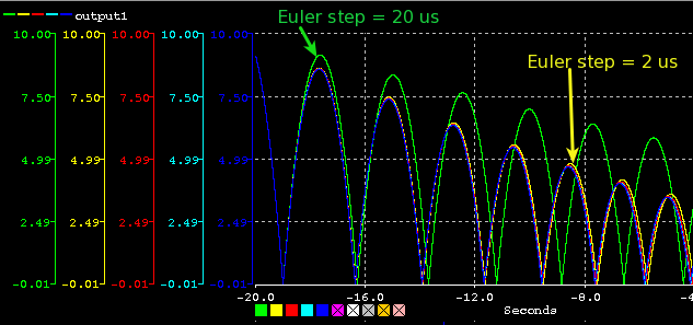
| Here we display the ball height over time calculated by the model. You can see that after the first bounce,
the calculations start to differ significantly showing the effect of the fixed step used by the model. |
 |
Tid Column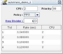
Multirate Simulink models have some number of threads that run at rates that are whole multiples of the model’s base rate. These threads are numbered from 1.
Rate (sec) Column
Displays the rate (in seconds) that each thread runs at. This is set when the Simulink model is created and built and cannot be modified here.
CPU Column
The CPU assigned to each thread. This may be edited here by double-clicking on the cell and typing in a new CPU number.
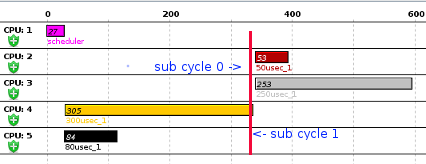
Freq Divider/Run At Cycle
When the frequency divider is > 1the user can specify at which of the sub cycles between 0 and FrequencyDivider -1
the model will be run. In this way, execution of the models can be interleaved.
The Run at Cycle value defaults to 0. A value between 0 and FrequencyDivider - 1 must be entered.
|
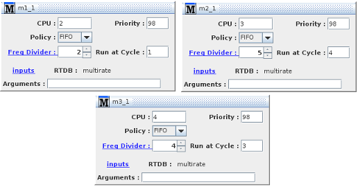 |
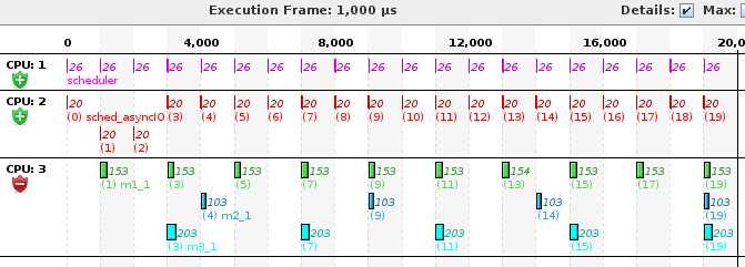
As can be seen from the execution time displayed in the RTViewer where all 3 models are running on CPU 3,
m1_1 runs every other cycle but at the second of those 2 cycles.
Model m2_1 runs every 5 cycle but at cycle number 4 and model m3_1 runs at the 3rd cycle of every four.
|
|
Model Data Exchange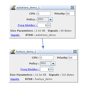
For Simulink© models defined as part of the test, it is possible to configure a model so that its inputs are connected to the outputs of other Simulink© models that are
part of the same test. I.e. before the model execution, the values of the outputs of the other model are copied to to the input values in the RTDB.
Simulink© models will show an inputs link in the model block.
Data exchange between models is completely independent of execution dependency.
So for instance if model A and model B execute concurrently (no execution dependency), you must be aware that the inputs of model B that come from the output of model A will only take effect in
the next test frame. I.e. you will have introduced a one frame delay on model B.
Connecting Model Outputs to Model Inputs
Click on the inputs link to connect. Be aware that you are setting the inputs on the model you click on so that the same output from a given model can
be connected to inputs of different models.
When clicking on the link the connection dialog shown to the right is displayed. 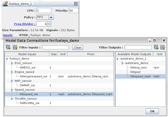
The list on the left is filled with the RTDB input items used by this model.
Clicking on an input item will select that input for connection and
will fill the list to the right with the list of outputs belonging to other models in the test.
Only the output items that have the same dimension as the selected input are shown. I.e. you cannot
set an input vector to the value of a scalar output and vice versa.
Connect an output to the selected input by clicking on the specific RTDB item. The connection will be shown on the input side by the content of the From column.
To clear an existing connection, select the input item and hit the Clear button.
If the item lists are too long, you can filter what is shown by entering a regular expression in the Filter Inputs|Outputs fields. Hit <ENTER> for the filter to take effect.
Note: The effect of the Alternate|Operator flag set on the output item is consistent with the behavior across the rest of SIMulation Workbench.
In this example where the engine speed in model fuelsys_demo is set from the output of model autotrans_demo_1,
if we set the value of autotrans_demo.SWspeed_mph via the RTViewer, an HMI display or the test script, the alternate value is set, the CVT value is not affected and
the Alternate or Operator flag is set on the output item.
The embedded copy routine that sets the input into model fuelsys_demo_1 will look at the flag and use the alternate value of the output
item to set the input value for the item fuelsys_demo.Engine_speed.SWenginespeed_sw.
|
Unit Conversion
Data flowing from one model to another via input/output connections is converted from the unit defined for the output item
to the unit used by the input item. The units specified for the items must be built-in units known to SIMulation Workbench.
The units are assigned to items of analog type in the item creation panel. The unit specified in the panel is entered by the user as free text but
only supported units can be converted. Units that belongs to the same class - speed, length, etc. - can be converted into one another.
When non-conformant units are specified for connected items, a warning message is issued in the Control Center message window and the conversion is
not performed.
When units are not specified, not conformant or unknown and engineering conversion is specified in the analog point configuration panel,
the conversion specified is used on the input item.
Example
- Analog out:
Unit: 'dummy' (unsupported)
Unit: 'km' (built-in length class)
- Analog in:
Unit: 'm/s' (built-in speed class)
EU conversion set with A:2 and B:10
Output unit 'dummy' is not supported and unit 'km' cannot be converted to a speed so the EU factors will be used:
If output value == 10, input value == 10*2+10 == 30
If input EU conversion is not set we have:
output value == input value == 10
|
Data Exchange and Unit Conversion Flow Chart
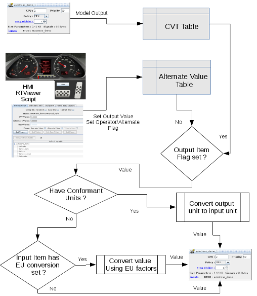
|
Model Specific RTDB
A Simulink© model is always compiled against a specific version of an RTDB. The model does not make SimWB API calls to read/write values from/to the RTDB.
Instead, the model accesses the RTDB by mapping the shared memory instance of the CVT table corresponding to the RTDB into the model process space. In this way a the model references the CVTTable
by executing code such as:
- local value int model = cvtTable.rtdb_input where rtdb_input is the name of an item in the RTDB.
or
- cvttable.rtdb_output = model calculated value
The cvtTable is a 'C' struct that is automatically generated when saving or updating the RTDB in the Control Center.
Access to the CVT table in this fashion provides the fastest access possible to the RTDB.
The disadvantage of this method is that the model needs to be recompiled whenever the RTDB is updated in the Control Center since the 'C'
struc that represents the CVT table might have changed.
Beginning with SIMulation Workbench 2018.1, it is now possible for each Simulink© model to have their own RTDB. The model specific RTDB will be merged
into the shared memory RTDB when the model is loaded. So as long as this RTDB is not modified, it is now possible to add,modify items into the main test RTDB
without affecting the RTDB in use by the model. with this mechanism, the model can only have access to its 'embedded' RTDB and cannot have access to other model
specific RTDB.
Model Independent Execution Chains
Dependent Chains
|
Independent Chains
|
|
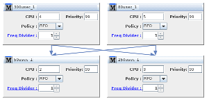
It is now possible to link model execution in independent chains. When models execution is predicated on previous models having finished running , models no longer
have to wait for all models in the previous sub-cycle to finish executing before the models in the next model sub-cycle are run.
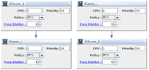
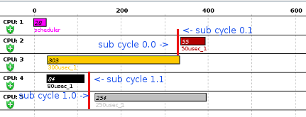
Notice how in the "Dependent Chains" pictures, the 2 bottom models starting execution is conditioned on both top models having finished running and note how the 250 μsec model execution is pushed
to start after the 300 μsec model is finished executing. It means that we waste 220 μseconds of execution between the end of
the 80 μsec model and start of the 250 μsec model.
By contrast in the "Independent Chains" pictures , the 50 μsec model will start as soon as the 300 μsec model in front has finished and likewise for the 250 μsec model
that will start running as soon as the 80 μsec model is finished. Because we no longer have the 220 μseconds gap, the model loop is finished executing at around 400 μ seconds whereas the old loop
would finish at around 600 μ seconds.
Snapshot Settings
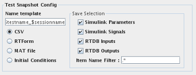 This pane sets the default configuration for RTDB snapshots. This can also be accessed from the Test session run sub-panel.
An RTDB snapshot takes the values of all RTDB item specified and saves it to a file with the given format. Snapshot can be saved as CSV (comma separated variables), RTForm (RTViewer forms),
MAT (V 5.0 file) or initial condition files.
You can take a snapshot of the RTDB while a test is running - See Note below- or configure your test session to take a snapshot at the end of the test run.
Take a snapshot of the RTDB by clicking on the  button in the Control Center toolbar.
Name template
This defines how to create the name of the snapshot file. Special tokens in the template name will be substituted with their value when creating the file.
The following are the known tokens :
$testname : The name of the running test. E.g. autotrans
$sessionname : The name of the running session. E.g. Ses_0024
$seqnum : A sequence number that is incremented every time the file is saved.
$framecount : The value of the simulation frame count when the snapshot was taken.
$time : The time of day when the when the snapshot was taken. E.g. 10-22-54
$date : The date of day when the when the snapshot was taken. 2015-10-12
Save Selection
This defines how to select the specific RTDB item that will be taken in the snapshot.
Simulink Parameters: Include Simulink model parameters in the selection.
Simulink Signals: Include Simulink model signals in the selection.
RTDB Inputs: Include all RTDB items defined as input.
RTDB Outputs: Include all RTDB items defined as output.
Item Name Filter: This is a regular expression used to match the name of the RTDB item. If the RTDB item name matched the regular expression,
the item will be included in the snapshot. E.g [E|e]ngine|throttle
Note: The snapshot of the RTDB is taken by the SimWB scheduling process (sched) as part of the asynchronous input process mechanism.
This allows SimWB to take the SimWB atomically when no other processes write to the RTDB. This ensure consistency in the snapshot taken.
However, taking snapshot of a large RTDB at run-time could trigger overruns in the simulation loop.
|


 (close) button in the upper right corner.


 This pane sets the default configuration for RTDB snapshots. This can also be accessed from the Test session run sub-panel.
 button in the Control Center toolbar.
