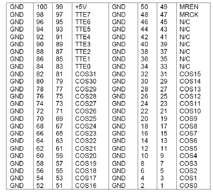
PAS2080 is an unusual card. First, it is treated as a pair of devices (for historical reasons). The user must always add both PAS2080:In and PAS2080:Out for each PAS2080 card installed on the system. Second (also for historical reasons), the user configures the I/O point mappings by editing a configuration file. All the PAS2080 cards installed on the system are configured with a single configuration file. Each real-time database has a separate configuration file.
CS-PAS-2080-000.
WCS-PAS-2080.
ICS-SWB-1224.

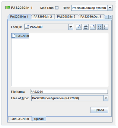
The Upload tab is used to upload the PAS2080 configuration file or tooth profile files to the current real-time database (see New/Select RTDB... for details on selecting the current real-time database). Select PAS2080 Configuration (PAS2080) or PAS2080 Tooth Profile (*.pos) in the Files of Type combo box, select the file then click on the Upload button.
The file is uploaded right away, without the Apply button needing to be pressed. When a configuration file is uploaded, the form will switch to the Edit PAS2080 tab and the file will be parsed to create the mappings. The mappings will not be applied to the RTDB until the Apply button is pressed.
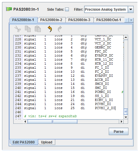
The Edit PAS2080 tab lets the user edit the configuration file. The changes to the configuration file and I/O point mappings are not saved to the RTDB until the Apply button is pressed. The file is parsed as the user types, creating the I/O mappings immediately. Pressing the Parse button is not necessary, unless the user has edited the I/O points in other forms. In that case, pressing the Parse button will re-parse the file and update the mappings.
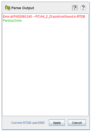
Any error or warning messages from parsing are shown on the right-hand side of the I/O Mappings form. Errors are displayed in red, and that line is ignored when creating mappings. Warnings are in orange, but the line generating the warning is still processed.
Comments are preceded by the # character. The # and the remainder of the line is ignored as a comment.
The configuration file lines are composed of “words” (predefined keywords, RTDB variable names, etc.), which must be separated by “white space” (any combination of one or more spaces or tabs). Each line is a single “statement.”
Designates the master board.
master board
The boards are numbered from 0. This is in contrast to the way SimWB numbers boards, from 1. Take this into account when editing the configuration file.
Defines a pulse width modulation output signal.
signal board [i]tte channel dty dutyPoint periodPoint
The 2080 board number. The boards are numbered from 0. This is in contrast to the way SimWB numbers boards, from 1. Take this into account when editing the configuration file.
Using itte instead of tte specifies inverting the output signal and logged value.
Specifies the 2080 channel number (0-7).
Specifies an analog output point containing the duty cycle as a fractional percentage (0-1) of the cycle period.
Specifies an analog output point containing the cycle period (10 or more) in microseconds.
signal 0 tte 6 dty TSS_DC TSS_PERIOD
signal 0 tte 7 dty OSS_DC OSS_PERIOD
signal 1 tte 0 dty GENLI_DC GENLI_PERIOD
Defines a toothed wheel output signal.
signal board [i]tte channel tw speedPoint anglePoint profile [biasPoint]
The 2080 board number. The boards are numbered from 0. This is in contrast to the way SimWB numbers boards, from 1. Take this into account when editing the configuration file.
Using itte instead of tte specifies inverting the output signal and logged value.
Specifies the 2080 channel number (0-7).
Specifies an analog output point containing the speed (0 or higher) in RPM.
Specifies an analog output point containing an angle (0 or higher) in degrees.
Specifies a profile file that has been uploaded to the RTDB.
Specifies an analog output point containing the optional angle bias in degrees.
The profile file contains a white space delimited list of values.
The first value is the maximum angle.
The following pairs of values consist of an angle followed either by a 0, indicating a falling edge, or by a 1, indicating a rising edge.
max-angle
angle1 0|1
angle2 0|1 angle3 0|1
...
See Upload Tab for details on uploading profile files to the RTDB.
signal 0 tte 0 tw ENGINE_SPEED PCRANK crank.pos
signal 1 tte 1 tw ENGINE_SPEED PCRANK cid1.pos CAMACT_1
signal 1 tte 2 tw ENGINE_SPEED PCRANK cid2.pos CAMACT_2
Turns a pulse on or off based on the value of an analog or digital output point.
signal board [i]tte channel do valuePoint
The 2080 board number. The boards are numbered from 0. This is in contrast to the way SimWB numbers boards, from 1. Take this into account when editing the configuration file.
Using itte instead of tte specifies inverting the output signal and logged value.
Specifies the 2080 channel number (0-7).
Specifies analog output point containing a zero or non-zero value indicating false or true or a digital output point.
signal 0 tte 0 do BRK_ACT_DO
signal 1 tte 1 do DRV_PRES_DO
The cos keyword stands for “change of state”.
Defines a pulse width modulation input signal.
signal board [i]cos channel dty dutyPoint periodPoint timeout
The 2080 board number. The boards are numbered from 0. This is in contrast to the way SimWB numbers boards, from 1. Take this into account when editing the configuration file.
Using icos instead of cos specifies inverting the input signal to be inverted before processing. The logged data will not be inverted.
Specifies the 2080 channel number (0-31).
Specifies an analog input point that will be set to the duty cycle as a fractional percentage (0-1) of the cycle period.
Specifies analog input point that will be set to the cycle period (0-0xffffffff) in microseconds.
Specifies the timeout (in microseconds) after which the duty analog point will be set to 0 or 100% and period analog point will be set to 0.
signal 0 icos 24 dty FPC_DC FPC_PERIOD 500000
signal 0 icos 25 dty CANVNT_DC CANVNT_PERIOD 500000
signal 0 icos 26 dty EVMV_DC EVMV_PERIOD 500000
signal 1 icos 0 dty HTR_11_DC HTR_11_PERIOD 500000
signal 1 icos 1 dty HTR_21_DC HTR_21_PERIOD 500000
Defines a pulse input signal.
signal board [i]cos channel pulse pulsesPoint latchPoint [options]
The 2080 board number. The boards are numbered from 0. This is in contrast to the way SimWB numbers boards, from 1. Take this into account when editing the configuration file.
Using icos instead of cos specifies inverting the input signal to be inverted before processing. The logged data will not be inverted.
Specifies the 2080 channel number (0-31).
Specifies an string input point containing the following C-structure:
struct {
int np; // number of pulses (0-30)
int overflow; // 0 or 1 (1 if more than 30 pulses since last read)
// np and overflow must be zeroed by the model.
unsigned long long onT[30]; // microseconds
unsigned long long offT[30];
double onLatch[30];
double offLatch[30];
} pulses
The pulsesPoint must be less than 1024 bytes (currently 968). Pulses are ignored during overflow. A model must clear the data each test cycle. The structure contains the exact time and latch values of the edges of up to 30 pulses that completed during the previous simulation test cycle.
np is the number of pulses that completed during the previous simulation test cycle. Up to 30 such pulses may be counted.
overlow is set to 1 to indicate that more than 30 pulses were encounted during the previous simulation test cycle.
onT and offT are, respectively, the timestamps of the beginning and end of each pulse that was counted.
onLatch and offLatch are, respectively an estimate of the latch value at the beginning and end of each pulse that was counted. The latch value is sampled from latchPoint each simulation test cycle, and the latch value of each edge is calculated using linear interpolation between the sampled latch values from the timestamps of each edge. When a model sets the value of latchPoint, it is setting its value for the end of the current test cycle.
See String Variables for details on accessing the fields of string variables within
Specifies analog output point that contains the value that will be latched at the edge times. The latch value is read at the beginning of every simulation cycle by the input task. A model or script should set it to the appropriate value for the end of the current test cycle. The latch value of edges is calculated as a linear interpolation based on the timestamp of the input signal’s edge.
Specifies options to modify the behavior of the pulse counting.
Defines an optional window based on the latch value that defines when to process the pulses (i.e., a “validity window).
low,high represents the low and high values between which pulses are recorded. Only pulses whose latch values are between these values are counted. If not specified, pulses are always counted until cleared by a model.
rollover represents the value at which the value at which the latch will “rollover”, that is reset to 0. This is used in the interpolation calculation since latchPoint is sampled only once per simulation test cycle, and latch values of edges are interpolated between those samples.
Specfies that pulses that last less than min microseconds are to be ignored.
signal 2 icos 16 pulse INJ_1_DATA CRANK LATCH=360,720,720
signal 2 icos 17 pulse INJ_4_DATA CRANK LATCH=720
signal 3 icos 19 pulse INJ_2_DATA CRANK LATCH=360,720 MIN=400
signal 3 icos 20 pulse INJ_2_DATA CRANK
Defines edge as a digital input signal.
signal board [i]cos channel di valPoint
The 2080 board number. The boards are numbered from 0. This is in contrast to the way SimWB numbers boards, from 1. Take this into account when editing the configuration file.
Using icos instead of cos specifies inverting the input signal to be inverted before processing. The logged data will not be inverted.
Specifies the 2080 channel number (0-31).
Specifies an analog input point that will be set to 0 or 1 or a digital input point that will be set to false or true.
signal 0 icos 3 di HTR_22_DI
signal 1 icos 25 di SS_1_DI
signal 1 icos 26 di SS_2_DI
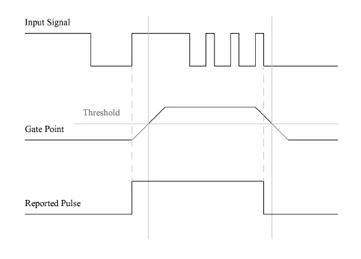
Counts pulses using a gated digital input signal. A gate value will be used to enable or disable counting of pulses. A pulse starts with the last rising edge before the gate value rises above the threshold value and ends with the last falling edge before the gate value falls below the threshold value.
signal board [i]cos channel gate gatePoint threshold latchPoint resPoint
The 2080 board number. The boards are numbered from 0. This is in contrast to the way SimWB numbers boards, from 1. Take this into account when editing the configuration file.
Using icos instead of cos specifies inverting the input signal to be inverted before processing. The logged data will not be inverted.
Specifies the 2080 channel number (0-31).
Specifies an analog output point that contains a value that will be used to enable the reporting of pulses.
Specifies a value that gatePoint must exceed in order to enable reporting of pulses.
Specifies analog output point that contains the value that will be latched at the edge times. The latch value is read at the beginning of every simulation cycle by the input task. A model or script should set it to the appropriate value for the end of the current test cycle. The latch value of edges is calculated as a linear interpolation based on the timestamp of the input signal’s edge.
Specifies an string input point that contains the following C-structure:
struct {
int ne; // number of edges (0, 1, or 2)
int overflow; // 0 or 1 (1 if another pulse starts before read)
// ne and overflow must be zeroed by the model.
unsigned long long onT; // timestamp in microseconds
unsigned long long offT;
double onLatch;
double offLatch;
} pulses
ne is the number of reported edges pulses encountered during the previous simulation test cycle. Only 2 edges may be reported.
overlow is set to 1 to indicate that another pulse has started in the same simulation test cycle.
onT and offT are, respectively, the timestamps of the beginning and end of each pulse that was counted.
onLatch and offLatch are, respectively an estimate of the latch value at the beginning and end of each pulse that was counted. The latch value is sampled from latchPoint each simulation test cycle, and the latch value of each edge is calculated using linear interpolation between the sampled latch values from the timestamps of each edge. When a model sets the value of latchPoint, it is setting its value for the end of the current test cycle.
See String Variables for details on accessing the fields of string variables within
signal 0 cos 30 gate ANACH0 1.25 CRANK RESULT_PUL0
signal 0 cos 31 gate ANACH1 3.75 CRANK RESULT_PUL1

|
OPTO 32 | PAS 2581 |

|