PAS 2581
Resistor simulation output board.
 The 2583/RES is a two channel resistor simulator IndustryPack (IP) module
offering a range from 0 to 39,999.75 ohms in quarter (0.25) ohm steps. The
2583/RES uses solid state relays to selectively short elements of a resistor
ladder; the earlier 2581/RES IP module used reed relays for this purpose.
The 2583/RES is a two channel resistor simulator IndustryPack (IP) module
offering a range from 0 to 39,999.75 ohms in quarter (0.25) ohm steps. The
2583/RES uses solid state relays to selectively short elements of a resistor
ladder; the earlier 2581/RES IP module used reed relays for this purpose.
This release supports these modules mounted on a Dynamic Engineering PCIe5IP
carrier; earlier releases supported these modules mounted on Acromag APC8620
PCI or APCe8650 PCIe carriers. Concurrent mounts a Dsub-25 female connector
on the PCIe5IP supporting four IP modules mounted on positions 'B' thru 'E'.
The 'A' slot position is taken up by the Dsub connector.
The Dynamic Engineering kernel drivers and generic IP API are based on their
de_PCiNIP version 1.1.2 and libipxxv 1.0.7 releases.
The API library provided by this software continues to be named 'lib2581'
for compatibility with existing custom applications.
Depending on the ordered option, the board supports various resistor ranges that must be configured outside of SimWB.
Reference Information
I/O Card Model Number
PAS 2581.
I/O Driver Model Number
N/A.
I/O Module License:
ICS-SWB-1232.
External Configuration
The ‘hardware_configuration’ file used by SimWB to map channel numbers to Carrier
Card, IP Slot, and pas2581 channel numbers is documented in the included pas2581(7) man
page. This file must be created before attempting to use the pas2581 API library. Typically, the
file is included on the SOnnnnn.tgz Calibration File tarball included with the pas2581 distribution.
The file resides in the /usr/lib/config/lib2581 directory.
A sample hardware_configuration file is:
| #<channel> |
<address> |
<burder> |
<initial> |
<range> |
[<calibration filename>] |
| 0 | 1A1 | 1.43 | OPEN | 400 | PAS7342_R1 |
| 1 | 1A2 | 1.43 | OPEN | 400 | PAS7342_R2 |
| 2 | 1B1 | 2.10 | 100.0 | 2000 | PAS7337_R1 |
| 3 | 1B2 | 2.10 | 100.0 | 2000 | PAS7337_R2 |
| 4 | 1C1 | 1.43 | OPEN | 40000 | |
| 5 | 1C2 | 1.43 | OPEN | 40000 | |
A '#' in the first column indicates a comment.
<channel> is in the range of zero to an implementation maximum determined
by the number of supported carrier cards (6), the number of available
IP module positions (slots) on each card (4), and the number of channels
per card (2). That's 48, so the current maximum channel count is 47.
The <address> is a triplet of the carrier card ordinal (0..255, determined
by the carrier's DIP switch setting), the slot ID (A..E), and each module's
resistor number (R1, R2).
The resistance is the resistance from the DB-25 connector mounted
to the end of the Dynamic Engineering carrier outward, and is provided as a
convenience for the end user. Rather than having to keep track of this
additional resistance in the application code, it may be specified here and
the API software will factor it in when computing a new resistance value.
The <initial> resistance is programmed when the lib2583_open() call is
made. "OPEN" may be specified if the channel should be left in open
circuit mode at open or at reset.
The <range> value may only be one of the following: "400", "2000", or
"40000" for the original 2583/RES card or "10000", "70000", or "1000000"
for the alternate 1-mega ohm version, and is used with the two range
shorting relays to limit the number of relay contact in-circuit and the
number of calculations made when simulating a device such as a RTD.
The optional calibration filename is used to increase the accuracy of
the 2583/RES boards by allowing the API to use per-channel calibration
measurements when choosing which resistor elements to use and which to
short-circuit. The calibration file format contains the measured
resistance of each resistor ladder element and the overhead resistance
of the assembly for each of the three ranges for that channel when
installed on the carrier card -- the resistances are measured at the
DB-25 connector installed on the carrier.
All calibration files are to be located in the /usr/lib/config/IP2583
directory.
A full set of calibration files and a pre-configured hardware_configuration
file is typically supplied as part of a system order. This set of files
takes the form of a tarball archive, named SOnnnnn.tgz, where the nnnnn
is the sales order number for this system - for example: SO12345.tgz
To install this file, use the following sequence of commands:
     # mkdir /usr/lib/config/lib2851

   # zcat SOnnnnn.tgz | (cd /usr/lib/config/IP2583; tar -xf -)
See the Release Notes PDF file for more information.
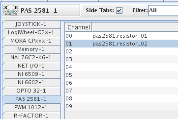
Mapping Table
Channel Column
Channel number.
Mapped Point(s) Column
Output point a channel is mapped to. To map a point to a channel, select a channel on the left side of the I/O Mappings form, then click on a check box for an I/O point on the right side of the form. See I/O Mappings... for details.
Connector
The 25-pin female D-Sub connector has the following pin assignments:
| Slot | Resistor | Pins |
| Slot A | Resistor 1: | 2 & 15 |
| Slot A | Resistor 2: | 3 & 16 |
| Slot B | Resistor 1: | 4 & 17 |
| Slot B | Resistor 2: | 5 & 18 |
| Slot C | Resistor 1: | 6 & 19 |
| Slot C | Resistor 2: | 7 & 20 |
| Slot D | Resistor 1: | 8 & 21 |
| Slot D | Resistor 2: | 9 & 22 |
| Slot E | Resistor 1: | 10 & 23 |
| Slot E | Resistor 2: | 11 & 24 |
Ground Pins: 1, 13, 14, 25

