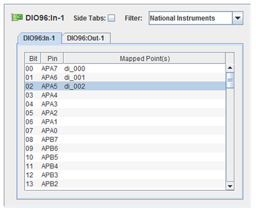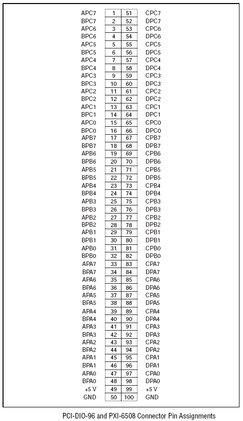
The DIO96 is a digital I/O board. Each channel represents a single boolean value that may be mapped to a digital I/O point. This configuration of the DIO96 configures the entire board as either input or output. SimWB considers the first four boards as input and boards five and higher as output.

CS-NI-PCI-DIO-96.
WCS-NI-PCI-DIO-96.
ICS-SWB-1215.
Concurrent’s DIO96 device driver allows you to associate a PCI address or board number with a specific /dev entry. In this way, when a program requests to open card five, for example the driver knows to talk to the second physic card in the system.
The assocation between board number and physical boards is defined in /usr/local/CCUR/drivers/d96/driver/d96_devs. To use a board as input or output, even if you have less than five physical boards in the system, edit a sample entry in this file and uncomment it. Reload the driver after modifying this file.
See also NI DIO96 for an alternate driver.
The synchronous dio96in digital input process reads all 96 input bits on a single PCI-DIO96 hardware board. Once instance of this process is run for each input board configured in the RTDB.
The synchronous dio96out digital output process writes all 96 output bits to a single PIC-DIO96 hardware board. One instance of this process is run for each output board configured in the RTDB.
Digital channel number.
Label of the pin for the digital channel.
I/O point(s) a bit is mapped to.
To map a point to a bit, select a bit on the left side of the I/O Mappings form, then click on a check box for an I/O point on the right side of the form. See I/O Mappings... for details.

The digital input and output processes read all 96 input bits and all 96 output bits (respectively) of a single PCI-DIO96 hardware board. Once instance of one of these processes is run for each board configured in the RTDB.
The PCI-DIO96 hardware board can be used for either input or output. However, the simulation software and dio96xx tasks do not support sharing inputs or outputs on the same board. As a result, a PCI-DIO96 board is always either all inputs or all outputs. By convention, the simulation software always assumes that the first four boards in the system are input and the next two boards are output. Board 1 thus corresponds to OS device /dev/d960_[1-4], board 2 to /dev/d961_[1-4], etc. See documentation of the d96 device driver for how to assign PCI bus location to specific board number.
The Concurrent™ Corporation device driver for the DIO-96 allows the user to associate a PCI address or board number with a specific /dev/ entry so that when a program wants to open card # 5 for instance, the driver knows it has to talk to the second physical card in the system.
This association between board number and physical boards defined in the d96_devs file which resides in
/usr/local/CCUR/drivers/d96/driver
This is the usual location for all device drivers provided by Concurrent™.
Edit a sample entry in the file and uncomment it. Reload the driver after modifying the file.
You should now be able to use a board as input or output even you have less than 5 physical boards in the system.
Here is sample for some entries in the file
# e.g. assume 4 cards were detected by the driver:                            #
#      assume card 4 is located in bus=3, slot=12, func=0                     #
#                                                                             #
#       device=4   card=2                                                     #
#       card=2     device=5                                                   #
#       device=3   card=0                                                     #
#       device=1   bus=3, slot=12, func=0                                     #
#                                                                             #
#     In the above example, the following devices will be created.            #
#       /dev/d964_[0-3] device 4 assigned to card=2                           #
#       /dev/d965_[0-3] device 5 also assigned to card=2                      #
#       /dev/d963_[0-3] device 3 assigned to card=0                           #
#       /dev/d961_[0-3] device 1 assigned to card 4 in bus=3, slot=12, func=0 #
#                                                                             #
#     Note: card=1 is not assigned and hence cannot be accessed by the user   #

|
DDC 1553-67 | EB5100 FlexRay |

|