
CS-ES-CAN-405-x.
WCS-ES-CAN-405.
ICS-SWB-1212.
The CAN I/O boards ESD402, ESD405 and IXXAT600 support four input and output networks (channels). The IXXAT640 board supports an additional 4 LIN channels. Messages sent and received on these networks have an ID and up to 8 bytes of data for regular CAN and 64 bytes for CAN FD. I/O points may be mapped to fields within the 8/64 bytes of data.
Support for Peak Mini PCIe CAN FD board is via the SocketCAN interface.
This driver/I/O task does not support the Peak mini PCIe CAN card which is support under Socket CAN.
To run this I/O task, you need to have PEAK-CAN USB device. Please Download the PCAN drivers from here and install before using this SimWB IO task. PCAN driver version 7.15 or later works with kernels 2.x to 4.x. Usually the installation steps are as shown below:
tar –xzf peak-linux-driver-X.Y.Z.tar.gz
cd peak-linux-driver-X.Y.Z
make clean
sudo make install
To use Socket CAN, you must ensure the appropriate modules are loaded and correctly configure the relevant CAN interface. Use the tools provided by the canutils package (you may need to install it).
On the NVIDIA family of hardware, you must for example use something like the following script to configure a CAN interface.
 #!/bin/sh
sudo rmmod mttcan
sudo rmmod can-raw
sudo rmmod can
sudo modprobe can
sudo modprobe can-raw
sudo modprobe mttcan
On other platform you must load the peak module to support the Peak Mini PCIe CAN card.
 #!/bin/sh
sudo modprobe peak_pciefd
To set the baud rate of the channel you can run the command:
sudo ip link set can0 type can bitrate 500000 dbitrate 2000000 berr-reporting on fd on
The command to set the baud rate and the CAN FD baud rate and bring the interface up will be run by the SimWB I/O task.
Be aware that all baud rates are not supported by every type of CAN hardware.

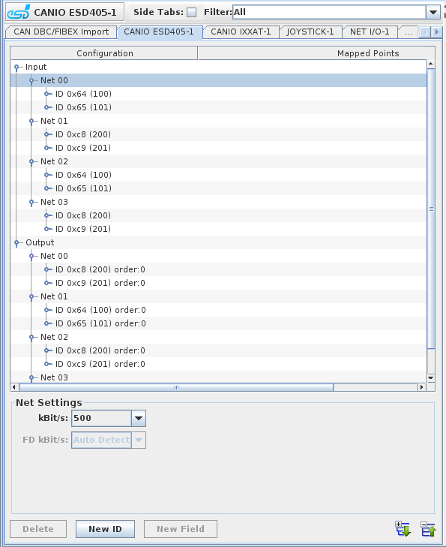
Expands the hierarchy tree showing board configuration.

Collapses the hierarchy tree showing the board configuration to show only the channel nodes.

Adds a new message ID for the selected network.

Adds a field to the selected label.

Deletes the selected node and everything, including mappings, below it. Networks cannot be deleted.
Specifies the data speed of the selected CAN channel in kBit/s.
For the IXXAT CAN boards and the ESD 402 board, the FD speed can also be set in the FD kBit/s combo box. This is only enabled when configuring a CAN FD supporting IXXAT/ESD CAN board. In addition, there is an option to specify choose Bosch's original protocol which is 'Non ISO CAN FD' and do not have stuff-bit counter bits in the CAN-frame. By default, we assume the messages conform to ISO standard 11898-2:2015, referred to as ‘CAN FD’.
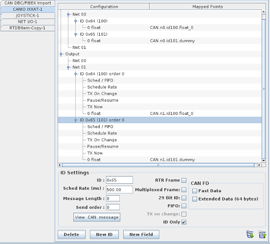
Create the CAN IDs that will be received / sent on the board specific channels.
The message identifier. This is an 11-bit value, unless the 29-Bit ID option is selected.
Specifies that the message is spread across multiple frames. One field within the frame is specified as the multiplexing variable that distinguishes between the messages with the same message ID.
Specifies that the message ID is a 29-bit value instead of an 11-bit value.
Specifies that the message is transmitted as soon as it changes. For output messages only. Not available for CANIO Peak.
The rate in milliseconds at which transmission is scheduled. For output messages only. Not available for CANIO Peak.
Specifies data length in message in bytes:
Define this CAN ID frame as a RTR frame. When the ID is an input, the user must enter the sched rate associated with this frame. The scheduling rate is the rate used to poll the remote station for the CAN ID message. For output frames, the sched rate field is disabled and the I/O task updates the content of the message every time the content is modified.
When checked, SimWB will only send or receive the CAN ID and no associated payload will be sent or received. Because of the fact that CAN IDs do not exist per se in the RTDB, an RTDB item must be mapped to the ID even though the mapping is ignored.
This is only supported on CAN FD supporting IXXAT and ESD CAN boards. When set, the data will be transmitted using the FD (Flexible data rate on the board).
This is only supported on CAN FD supporting IXXAT and ESD CAN boards. When set, the payload of the CAN message can be up to 64 bytes long.
Only the following lengths are valid:
0,1,2,3,4,5,6,7,8,12,16,20,24,32,48,64. A shorter message will be padded to the next allowable message size.
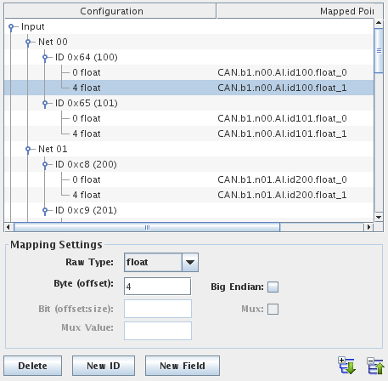
Define the mapping from subfields of the CAN message to individual RTDB variables. Add a mappable field by clicking on the New ID button.
How to interpret the raw bits of the field.
Integer bit field. Location is specified by the Bit setting.
One-byte integer. Location is specified by the Byte setting.
Two-byte integer. Location is specified by the Byte setting.
Four-byte integer. Location is specified by the Byte setting.
Four-byte floating-point number. Location is specified by the Byte setting.
Eight-byte floating-point number. Location must be specified as 0 by the Byte setting.
Byte offset within the 8-byte data of the non-bit field data.
Bit offset and size within the 64-bit data of the bit field data.
Interprets the bytes as most significant byte first.
Designates this field as the multiplexing variable that distinguishes between various frames having the same message ID when the ID’s Multiplexed Frame option is selected. One and only one field should have this option set.
Designates the value of the multiplexing variable to select which frame of a multiplexed message this field belongs to.
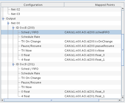
When creating a CAN output message, message control branches are automatically added. Those mappable controls are in addition and do not replace the SimWB API calls with the same
functionality. By mapping message control to RTDB variables, the model(s) - which have no direct access to the SimWB API - can directly control the CAN messages properties.
When mapping the Sched / FIFO, Schedule Rate etc. control branches to RTDB variables, the output message properties can be controlled directly by changing RTDB variable values. The values
of the connected variables are initialized to value corresponding to the properties of the messages. Thus, the value of the variables defined in the initial conditions
or the default value assigned when creating the RTDB variables do not apply.
The IXXAT 640 Board provides 4 LIN channels in addition to 4 CAN channels. Mapping information for these LIN channels is similar to that for the Lipowsky BabyLIN device.
|
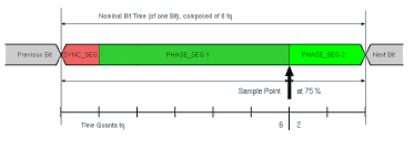
The IXXAT 600/640 Board provides provides the ability to set custom bit timing
so that the sampling point can be set. The sampling point defines in percent when the hardware sample the CAN bus during the duration of a bit.
|

|
This process packs all CAN raw output values corresponding to CAN output items and places them in the CAN output FIFO queue. The process will not queue a request into the FIFO queue if the raw CAN message is unchanged since the last test cycle.
The FIFO queue is read by the canasyncio asynchronous task that writes them to the hardware board.

|
CAN DBC Import | FlexRay Star Cooperation |

|