FlexRay Star Cooperation
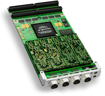
The Star Cooperation™ FlexRay board supports a maximum of 4 controller per card. Each controller supports both A and B channels to that the communication can be made redundant.
The FlexRay card is a PMC ii type card that is mounted on a PCI-e carrier board.
The FlexRay for individual channel is provided by a tiny flex module mounted on the main FlexRay board.
Reference Information FlexRay Star Cooperation
I/O Card Model Number
CS-ES-CAN-405-x.
I/O Driver Model Number
WCS-ES-CAN-405.
I/O Module License:
ICS-SWB-1212.
FlexRay Clusters and Controllers
Before you can start communicating on the FlexRay network, your FlexRay cluster and controllers need to be setup correctly. Failure to do so will prevent the FlexRay network to synchronize.
Refer to your FlexRay network configuration manuals in order to define compatible cluster and controller parameters to make your network work.
SIMulation Workbench™ releases provide several examples of working configurations. Those configuration are meant to be run in a loopback mode when channel 1 is looped back to channel 2.
|
All the parameters defining the FlexRay clusters and attached controllers can be configured independently throught the SIMulation Workbench™ Control Center GUI.
The FlexRay configuration can also be imported from a FIBEX xml file via the FIBEX FlexRay Import panel in the GUI.
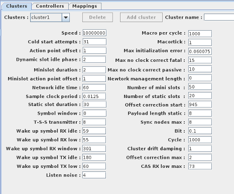
Cluster Definition
Clusters can be added / deleted from the configuration by clicking on the Delete / Add cluster buttons. The delete button will remove the cluster selected in the combo box. The cluster cannot be deleted
when it in use by any of the board controllers.
Refre to you FlexRay network documentation for the meaning of those parameters.
|
 |
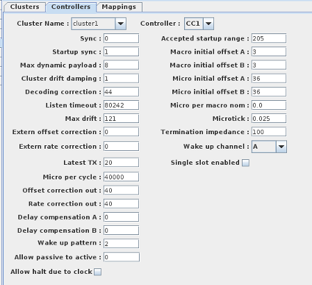
Controller Definition
The board supports a maximum of 4 controllers. The numbers of controllers on the board is specified by the number of channels given when adding the board to the SimWB configuration.
A controller must be associated with a specific cluster so the that the FlexRay network configuration is consistent across a given FlexRay cluster.
Click on the controller number in the controller combo box to select and configure the other controllers present on the FlexRay board.
|
 |
RTDB Mappings
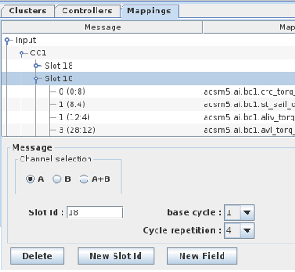
Before you can map RTDB items to FlexRay messages, you must first create the message frame that will be sent by the FlexRay controllers.
Each frame is identified by a Slot ID and its associated base cycle / repetition. A frame is created on a specific controller (CC1|CC2...) and is either an input or output frame.
Slot Id
Click on new Slot Id button to create a new FlexRay Frame.
Slot Id
Enter the slot Id in the Slot ID field.
Channel selection
Whether this specific FlexRay frame will go on the controller channel A, B or both (A+B).
Base Cycle
The base cycle for a specific FlexRay frame is constrained by its repetition value. I.e. a frame with a repetition of 1 will go at every frame, a frame with a repetition of 4 will go every 4 cycles.
The base cycle defines on which particular sub cycle this frame will go. I.e, for a reptition of 4, the base cycle can be
specified between 0 and 3 meaning that the frame will be sent either on the first(0) , second(1), third(2), or fourth (3) sub cycle.
Repetition
Click on the drop down box to specify the repetion rate for this specific frame slot Id. The repetition allowed under FlexRay are the values selectable in the drop down box.
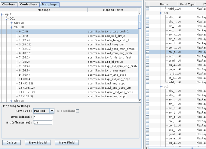
New Field
In order to map an RTDB item to a FlexRay frame, you must create a field on that frame at a specific offset.
Once the field has been defined with the frame, it can be mapped to a specific item in the RTDB.
Byte Offset
The byte offset within the FlexRay message where this item will be placed (output) or read from (input).
Bit (offset:size)
This is only use when the raw type for the field is packed. A packed item can occupy a range of bits in the specific 64 bit long word starting at the byte offset defined.
Most FlexRay signals are defined this way.
Raw Type
How to interpret the raw bits of the field.
- Packed: Integer bit field. Location is specified by the Bit setting.
- char: One-byte integer. Location is specified by the byte offset setting.
- short: Two-byte integer. Location is specified by the byte offset setting.
- int: Four-byte integer. Location is specified by the byte offset setting.
- float: Four-byte floating-point number. Location is specified by the byte offset setting.
- double: Eight-byte floating-point number. Location must be specified as 0 by the byte offset setting.
Big Endian
Interprets the bytes as most significant byte first.
I/O Tasks: flexrayout (,synchronous) flexrayio (asynchronous)
This flexrayout I/O task packs all FlexRay raw output values corresponding to FlexRay output messages. It places the messages in the Flexray output FIFO queue.
The FIFO queue is read by the flexrayio asynchronous task that will write the output messages to the flexray controller.
This same I/O task will also read the flexray messages coming on the flexray controllers. It will decode them according to the item mapping fields and will queue the update
to the asynchronous input queue so that the RTDB is updated during the next synchronous input cycle.


