ARINC429
Labeled messages are sent or received over each channel. I/O points are mapped to bit fields within these messages.
Reference Information
I/O Card Model Number
CS-DD-42916I3-300.
I/O Driver Model Number
WCS-DD-42916I3.
I/O Module License:
ICS-SWB-1211.
|
|
Buttons
Expand All
Expands the hierarchy tree showing board configuration.
|
 |
Collapse All
Collapses the hierarchy tree showing the board configuration to show only the channel nodes.
|  |
New Label
Adds a new message label for the selected channel.
|  |
New Field
Adds a field to the selected label.
|  |
Delete
Deletes the selected node and everything, including mappings, below it. The top level nodes cannot be deleted.
|  |
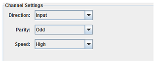
Channels
Direction
Selects the I/O direction of the channel. ARINC 429 channels are uni-directional,
so, a direction must be specified per channel. This setting is not persistent on the real-time host if no point is mapped to the channel.
Parity
Selects the parity of the channel.
Speed
Selects the speed of the channel.
- High : 100 kbits/s
- Low : 10 kbits/s
|
|
Channel Names
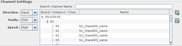
This sub panel allows you to name ARINC429 channels for easier identification.
The list box if filled with all available channels for all available boards configured in Simulation Workbench™.
To assign a name to a specific channel, click on the node corresponding to the channel you want to name and
double-click on the second table column to edit in place.
You can also search for a specific string in the channel name list by entering a search string in the
search channel Name entry field. The list will be filtered to only show the channels whose name matches the search string.
You can double click on the channel number in the list to position the mapping dialog on that channel.
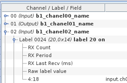
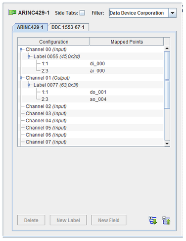
Once you have assigned a name to a channel, the name is displayed next to the channel number in
the mapping panel as shown in the image to the right where the channel name appears in bold characters.
|
Note: Be aware that both the channel names and the label names described below are
global in scope. They are not RTDB or project specific.
|
Labels
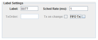
Label
Unique identifier for a message on this channel. Usually specified as an octal number.
To enter the label value as an octal number, prefix the number with 0 . To enter as a hexadecimal value, prefix the number with 0x
Enable SDI
When checked, additional mapping nodes are added for each allowable value of the 2 bit SDI field.
When enables the SDI bits (22,23) - (10,9) cannot be mapped to a RTDB signal.
Sched Rate (ms)
Rate at which messages are sent (output channels only).
FIFO Tx:
Specifies that messages are sent via FIFO instead of scheduled rate (output channels only).
Tx on change
Specifies that a message is sent only when the value changes (FIFO Tx only).
TxOrder
The priority to send this label when multiple labels are output on the same channel (FIFO Tx only)
|
|
Label Names
As with to the ARINC429 channels, the labels on specific channels can also be assigned a name to make it easier to identify the label purpose.
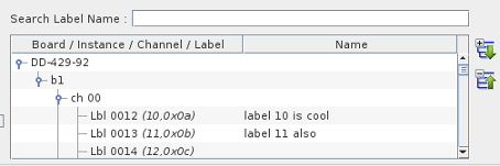
This list box is filled with all named ARINC 429 for all the ARINC429 boards configured in Simulation Workbench™.
To assign a name to a specific label, click on the node corresponding to the label you want to name and
double-click on the second table column to edit in place.
You can also search for a specific string in the label name list by entering a search string in the
search Label Name entry field. The list will be filtered to only show labels whose name matches the search string.
You can double click on the label number in the list to position the mapping dialog on that channel.
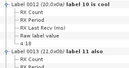
Once you have assigned a name to a channel, the name is displayed next to the channel number in
the mapping panel as shown in the image to the right where the label name appears in bold characters.
Mapping
Multiple bit fields of the 32 bit ARINC429 word (to the exception of the 8 bit label field and the parity bit) can be mapped to separate RTDB signals.
A bit field is specified by its start bit (in SimWB order) and its number of bits.
Bit (offset:size)
Bit offset and size of the field to be mapped to the selected RTDB variable. Only integer bit fields are supported. Single-bit fields are mapped to digital points. Multi-bit fields are mapped to analog points.
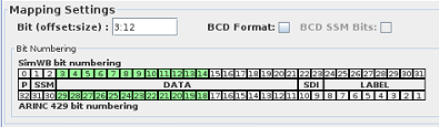
To be consistent with the bit-numbering of other devices in Simulation Workbench™ , bit-counting/numbering always starts at 0 (Most Significant Bit) and increases to the Least Significant Bit.
So, for instance, in a 32-bit word, the MSB is always bit 0 and the LSB is bit 31. This will, in some case, not match the device-specific bit numbering. And the user may have to
convert from the device-specific bit numbering to the SimWB-specific bit numbering.
To make the conversion from SimWB bit numbering to ARINC 429 easier, the mapping dialog shows the bit layout in the ARINC word.
For each bit field created, the bits specified are also highlighted in green.
The bottom row shows the bit numbers according to the ARINC429 bit numbering convention.
BCD Format
Specifies that bits 3 through 21 are interpreted as a BCD value.
BCD SSM Bits:
Specifies that bits 1 through 2 are interpreted as an integer value.
Mapped Point(s) Column
I/O point(s) a field is mapped to.
To map a point to a field, select a field on the left side of the I/O Mappings form, then click on a check box for an I/O point on the right side of the form. See I/O Mappings... for details.
Mappable Controls
To facilitate handling of the label mode of transmission or monitor label reception, additional mappable controls are associated with each individual label. Those controls
can be mapped to RTDB signals so that setting those signals will affect the transmission of the label or statistical information about the label reception will be set in the associated input signal.
Output
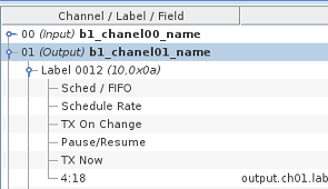
5 mappable controls that affects the label transmission are provided.
- Sched / FIFO : set to 1 to transmit the label according to the scheduling rate specified when creating the label. Set to 0 to transmit the label in FIFO mode.
- Schedule Rate : This controls can be used to change the scheduling rate (ms) that was initially configured when creating the label.
- TX On Change : If the label is in FIFO mode and this is set to 1, the label will be transmitted whenever the content of the 32 bit arinc word changes.
- Pause / Resume : Set to 1 to pause sending the label. set to 0 to resume sending the label.
- TX Now : If the label is in FIFO mode, it is transmitted only when TX On Change is set and its value changes. When TX On Change is not set, a transmission of
the label can be forced by setting this to 1. The value is reset to 0 after each transmission.
Input

4 Mappable controls are provided.
- RX Count : The mapped variable will have the reception count for the label since the beginning of the test.
- RX Period : This is the time elapsed since the previous reception of the label. Be aware that this value is updated only after reception of the label. In other word, this will not increase if the label stops coming in
- RX last Recv : This is the amount of time since the beginning of the test when the label was last received.
- Raw label value : The mapped RTDB signal will contain the raw 32 bit value of the received label.
Synchronous I/O Task: arinc429out
The process computes all ARINC 32-bit output words corresponding to ARINC 429 output items and places them into the ARINC output FIFO. ARINC words that are unchanged since the last test cycle will not be queued.
The FIFO is read by the arinc429asyncio asynchronous task that writes them to the hardware board.
Asynchronous I/O Task: arinc429asyncio
This process runs asynchronous to the simulation loop and handles both inputs from and outputs to the ARINC 429 board. Due to the fact that an ARINC board can only be opened by one task at a time and a single board can be configured to do inputs and outputs simultaneously, this process is multi-threaded.
There is a separate thread for each board that is configured as input (that is, at least one channel on the board is configured for input and at least one RTDB variable is mapped to that channel). The input thread configures the board to notify itself of any new inputs received via a software interrupt. The thread sleeps until the interrupt wakes it. It then reads the interrupted channel immediately and queues an update request into the asyncio FIFO queue. In this mode, the input thread does not poll the board to detect new inputs.
There is a single thread to handle the outputs for all the boards that are configured as output (that is, at least one channel on any board is configured for output and at least one RTDB variable is mapped to that channel).
The output thread polls the ARINC output FIFO at a regular intervals. The default polling interval is 5 milliseconds and can be specified as a command line argument with –t msec in the Options column of the I/O Tasks form.
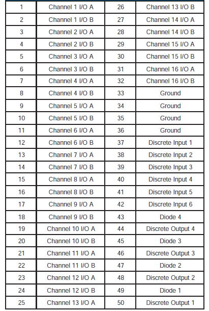
DDC ARINC429 Connector