A one-, two-, or four-channel card which provides Bus Controller (BC), Remote Terminal (RT), and Bus Monitor (BM) operating modes. The 106K board only supports BC ,RT or BM functionality on any single channel. On the 206K board, BC and Multi RT can be run on the same channel. Nevertheless, Bus Monitor must always run on a channel by itself. SimWB supports the exchange of messages on the 1553 bus via the Box Car approach. That is, the message’s transmission and reception requests occur at regular intervals that is specified when creating the message.
CS-AM-APE-1553-x.
WCS-DD-67106K or WCS-DD-67206K .
ICS-SWB-1225.
Expand AllExpands the hierarchy tree showing board configuration. |  |
Collapse AllCollapses the hierarchy tree showing the board configuration to show only the channel nodes. |  |
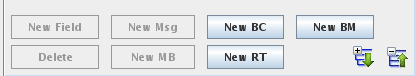
New BCDesignates the selected channel as a bus controller. |  |
New RTAdds a remote terminal definition to the selected channel |  |
New BMDesignates the selected channel as a bus monitor. | 
|
New MsgAdds a message definition to the selected bus controller or bus monitor. | 
|
New MBAdds a mailbox definition to the selected remote terminal. | 
|
New FieldAdds a field to the selected message or mailbox. | 
|
DeleteDeletes the selected node and everything, including mappings, below it. Channels cannot be deleted. | 
|
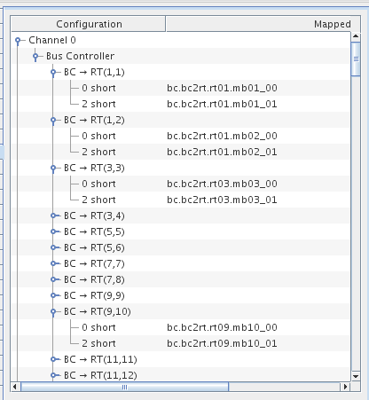
To define a channel as a bus controller, select the channel and click on the New BC button. Once a bus controller has been defined on a channel, you cannot add a remote terminal to that channel. Instead, you add message definitions to the bus controller.
To define a message for a bus controller, select the bus controller and click on the New Msg button. When a message is selected the following dialog appears below the mapping table:
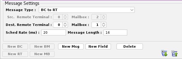
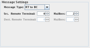
Selects the type of message. The message type appears in
Message sent from the bus controller to a mailbox of a remote terminal. The values sent to the remote terminal are defined by mapping output points to fields of this message.
Message read from a mailbox of a remote terminal by the bus controller. The values read from the remote terminal can be accessed by mapping input points to fields of this message.
Message read from one mailbox of a remote terminal to another mailbox of the some or another terminal. Fields cannot be mapped to I/O points for this message type.
Remote terminal and mailbox that RT to BC , RT to BC Async and RT to RT messages are read from.
Remote terminal and mailbox that BC to RT , BC to RT Async and RT to RT messages are written to.
Rate at which messages are scheduled, expressed in milliseconds between transactions.
Length of the message as a count of 16-bit words. The count must be between 1 and 32 16-bit words.
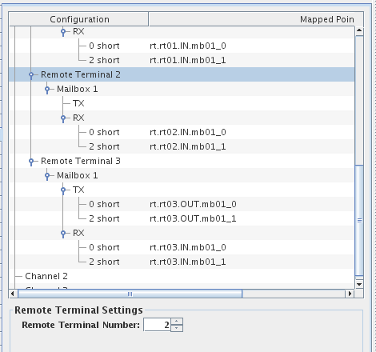
To define a remote terminal for a channel, select the channel and click on the New RT button. Once a remote terminal is defined, mailboxes can be defined for it. When a remote terminal is selected, the following dialog appears below the mapping table:
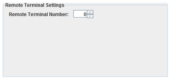
Defines the remote terminal number of this remote terminal. Two remote terminals on the same channel cannot have the same number.
To define a mailbox for a remote terminal, select the remote terminal and click on the New MB button. Once a mailbox is defined, fields can be created for mapping points to the messages that are sent to or read from the mailbox. When a mailbox is selected, the following dialog appears below the mapping table:
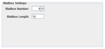
Number of the mailbox. Each mailbox in a remote terminal must have a unique number between 0 and 31. Note that mailbox numbers 0 and 31 are reserved for mode codes.
Length of the mailbox as a count of 16-bit words. Each mailbox must be between 1 and 32 16-bit words in length.
 |
|
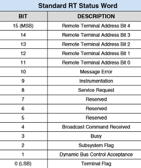
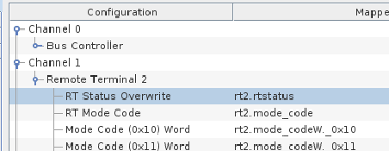
Bit 0 to 10 , where 0 is the least significant bit of the RT status word can be specified by the user by mapping the RT Status Overwrite branch under the Remote Terminal. When not mapped, the RT status bits are defined by the default behavior of the RT.
Be aware that bits 11 to 15 cannot be overwritten as they represent the Terminal address bits. Refer to the table to the right for the description of the RT status bits.
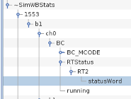
The RT status bits can be accessed from the Bus Controller by referencing the internal variables
~SimWBStats.1553.bX.chY.BC.RTStatus.RTZ.statusWord where :
The RT status bit word reflects the latest message between the specified RT and the Bus Controller. The status is also available under specified BC messages and in this case reflects the RT status word corresponding to the specific message.
To define a field in a message or mailbox, select the message or mailbox and click on the New Field button. When a field is selected, the following dialog appears below the mapping table:
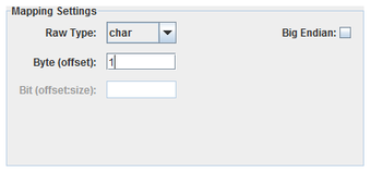
Specifies how to interpret the raw bits of the message field.
Integer bit field, specified with a byte offset to a 32-bit integer and a bit offset and size within that 32-bit field. Single bit fields are mapped to digital points, all others to analog points.
One-byte integer field, specified with a byte offset. Integer fields are mapped to analog points.
Two-byte integer field, specified with a byte offset. Integer fields are mapped to analog points.
Four-byte integer field, specified with a byte offset. Integer fields are mapped to analog points.
Four-byte floating point field, specified with a byte offset. Floating-point fields are mapped to analog points.
Eight-byte floating point field, specified with a byte offset. Floating-point fields are mapped to analog points.
Field’s offset in the message in bytes. For Packed, this is the offset of the 4-byte integer containing a bit field.
Bit offset and size of a Packed field within a 4-byte integer block. Bits are numbered from the high order bit of the 4-byte block. Which byte this bit is in is determined by the Big Endian setting. The offset is measured from the high order bit of the block to the high order bit of the field.
Interprets values as most significant byte first. This is the reverse of the default way data is handled on Intel x86 platforms.
To define a channel as a bus monitor,
select the channel and click on the New BM button.
Once a bus monitor has been defined on a channel, you cannot add a remote terminal or a BC to that channel.
Instead, you add message definitions to the bus controller.
To define a message for a bus monitor,
select the bus monitor and click on the New Msg button. When a message is selected the following dialog appears below the mapping table:
Configuration tree.
I/O point(s) a field is mapped to.
To map a field to a channel, select a field on the left side of the I/O Mappings form, then click on a check box for an I/O point on the right side of the form. See I/O Mappings... for details.
This process assembles all the 1553 output messages and places them into the aim 1553 output FIFO queue. A request will be added to the queue if the output message buffer is unchanged since the last test cycle.
The FIFO queue is read by the aim1553asyncio asynchronous task that writes them to the hardware board.
This process runs asynchronous to the simulation loop and handles both inputs from and outputs to the AIM 1553 boards. It acts as both a bus controller and a remote terminal when bus controllers and remote terminals have been configured for the device. This process is multithreaded.
There is a separate thread for each bus controller and remote terminal.
There is a single thread that processes all outputs to all AIM 1553 boards. The output thread polls the AIM 1553 output FIFO queue at a regular interval. The default interval is every 5 milliseconds and can be specified with the –t msec option in the options column of the I/O Tasks form.

|
Advantech PCIE-1758DIO | ARINC429.htm |

|