The General Standard 16AO16 is a 16 bit analog output board. Up to 16 channels are supported on the board.
The board can be ordered in either differential or single ended mode. In either case, the maximum number of channels on the board is 16. The 16AO12 is similar in functionality to the 16AO16 but only provides 12 channels and the voltage range cannot be set and is fixed at +/-10V.
The 16AO16 can be ordered with 4,8,12 or 16 channels. See Configured Devices Table for instructions on how to configure the number of channels.

CS-GS-16AO12x.
WCS-GS-16AO12.
ICS-SWB-1214.
CS-GS-16AO16x.
WCS-GS-16AO16.
ICS-SWB-1214.
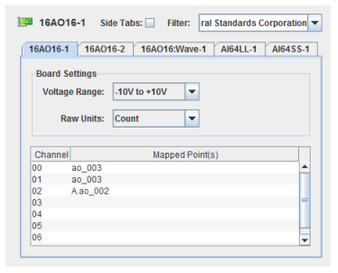
Selects the voltage range for all the channels on the board.
Selects the units of raw values as being either Count or Volt. This is the unit used to store the raw value in the SimWB RTDB for the mapped item.
When Volt is selected, the voltage read from the board is stored as the raw value in the RTDB. If your I/O point is defined with an associated engineering conversion, you must write the conversion to convert from volt to engineering unit. Without engineering conversion, the item value and raw value in the RTDB will be the same and expressed in volts.
When Count is selected, the unsigned 16-bit integer value read from the board is stored as the raw value. If your I/O point is defined with an associated engineering conversion, you must taken into account that the raw value range of 0 to 0xffff corresponds to the voltage range configured on the board.
Channel number.
I/O point(s) a channel is mapped to.
To map a point to a channel, select a channel on the left side of the I/O Mappings form, then click on a check box for an I/O point on the right side of the form. See I/O Mappings... for details.

The analog output process writes the 12 output channels to a single 16AO12 hardware board or the 16 output channels to a single 16AO16 hardware board. One instance of this process is run for each board configured in the RTDB.
| 16AO16:Wave |

|