The General Standard 16AO16 is a 16 bit analog output board. Up to 16 channels are supported on the board. See 16AO16 for details. In the 16AO16:Wave configuration, it is used as an arbitrary wave form generator.
CS-GS-16AO12x.
WCS-GS-16AO12.
ICS-SWB-1214.
CS-GS-16AO16x.
WCS-GS-16AO16.
ICS-SWB-1214.

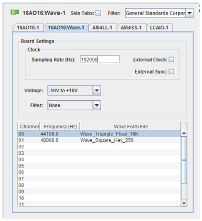
Rate at which the board outputs its sample. The maximum rate the board supports is 449.5 KHz.
Specifies the use of an external clock instead of the internal clock. This is usually used when multiple 16AO16:Wave boards are defined with one board providing the clocking for the other boards. This ensures that there is no drift between the various boards so they will all be perfectly in phase.
Specifies beginning output of the wave form when the board receives a low to high to low transition on its external sync pin. This is used to keep multiple boards perfectly in sync by starting all their output at the same time.
Selects the voltage range for all the channels on the board. The raw value is a 16-bit value whose range should can be mapped to volts using engineering unit conversions.
Selects the pass-band elliptical filter present on some 16AO16 boards used at initialization. The filter can also be changed at run-time via the SimWB API. The filter are common to all channels on the board.
55 KHz
145.6 KHz
Consult the General Standards web site for more information.
Channel Number.
Frequency at which the wave form file will be repeated on the channel.
Wave form file mapped to the channel.
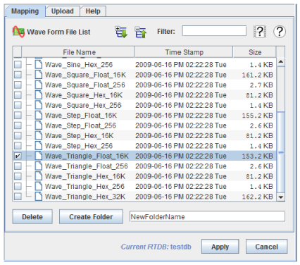
16AO16:Wave is one of the few boards to have an alternate form on the right hand side of the I/O Mappings dialog.
Instead of mapping channels to I/O points, wave files are mapped to each channel. The real-time host will interpolate the data points specified in the file via a DDS algorithm so that when the number of data points specified in the file does not match the number needed for the sampling rate, the correct wave form is still output.

Wave forms are mapped to the selected channel in the same way that I/O points would be on other boards. Select a channel by clicking on it, then click on the check box next to the wave file you want to map to that channel.
Deletes the selected wave file or folder.
Creates a new folder with the name specified in the adjacent text box in the folder selected in the Wave Form File List. If no folder is selected, the new folder will be in the root of the list. If a wave file is selected, the new folder will be in the folder containing the selected wave file.
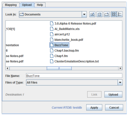
Uploads wave files to the real-time host.

Shows the destination folder on the real-time host.
Creates a symbolic link to the selected file on the real-time host. The Control Center must be running on Linux and the real-time host must have the source file system mounted in the same directory as it is on the client system.
Uploads the selected file to the destination folder on the real-time host.
Provides brief help on mapping for 16AO16:Wave devices.
Wave form files are in ASCII and are a list of voltage or raw values between the maximum and minimum voltage range specified. An example file specified using floating-point voltage values is:
FORMAT_FLOAT
-10.000000 -9.998779 -9.997559 -9.996338
-9.995117 -9.993896 -9.992676
-9.980469
An example file using unsigned 16-bit integer hex numbers to specify raw values is:
FORMAT_HEX
0000 0004 0008 000c 0010 0014 0018 001c
0020 0024 0028 002c 0030 0034 0038 003c
0040 0044 0
This process runs asynchronous to the test cycle and handles outputs to the GS 16AO16 board when the board is configured in the RTDB as a wave form board. The board has a maximum of 16 output channels. This process is multithreaded.
There is one main thread that processes commands from the command FIFO queue.
There are two additional threads that share the workload of output the wave forms continuously to the devices.
Contrary to most other hardware devices supported by SimWB, there is no mapping between RTDB variables and hardware channels on the board.

|
16AO16 | ADLINK 7256 |

|