PWM 1112 (Input)

The CP-PWM-1112 is an FPGA-based Pulse Width Modulation (PWM) input card by Concurrent Real-Time. This card is designed to capture pulse-width-modulated signals with high accuracy. With a timing resolution of 15.15 ns, and the ability to measure the frequency and duty cycle of a signal, this card is ideal for use in hardware-in-the-loop (HIL) applications.

This PCIe card has 12 TTL input channels, with a frequency range of 0.05 Hz to 660KHz. Each channel has programmable digital debouncing filters and pulse-width averaging. The base measurement frequency of the card is 66 MHz with a pulse-width accuracy of 30.30 ns. You can use multiple cards on a system.

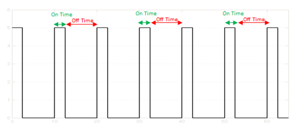
PWM 1112 Typical PWM Signal
Figure 1: Typical PWM Signal

Reference Information

I/O Card Model Number:

CP-PWM-1112.

I/O Driver Model Number:

WCS-PWM-1112.

I/O Module License:

ICS-SWB-1243.

Channel Settings

The following settings apply to all channels:


  • Debounce count
    Debouncing filter count, specified in the [0,127] range.
    • 0 - No filter is applied.
    • >0 - Filter input for glitches less than count x 30.30ns. If count is 1, glitches or frequencies above 33 MHz will be filtered out. If count is 127, glitches or frequencies above 250 KHz will be filtered out.

    PWM 1112 Debouncing Example
    Figure 2: Example of Input Signal Being Filtered Using Debouncing Filter

  • Average count
    Averaging rolling window length, specified in the [0, 127] range.
    A 127-element long FIFO queue can be used to accumulate the observed frequencies. The window length determines the FIFO length. The observed frequency is an average of the values stored in the FIFO queue.

I/O Device Mapping

As with any other SimWB I/O devices, connection between the RTDB and the PWM Input card is done via the GUI mapping dialog. For each of the 12 channels, you can map the following measurements to AI RTDB variables:

  • Pulse Count Input
    Number of pulses observed in a SimWB test frame.
  • Duty Cycle (%) Input
    Signal duty cycle, in percentage, calculated canonically as follows:
    Duty cycle(%) = (On Time / Period) x 100
    In the context of the PWM 1112 card, the duty cycle for a channel is calculated as follows:
    Duty cycle(%) = (high_clock_count/width_clock_count) x 100
  • Frequency (Hz) Input
    Signal frequency, in Hz. channel.

Pin Assignment

PWM 1112 Pinout

PWM 1112 I/O Mapping Pane

See Also: