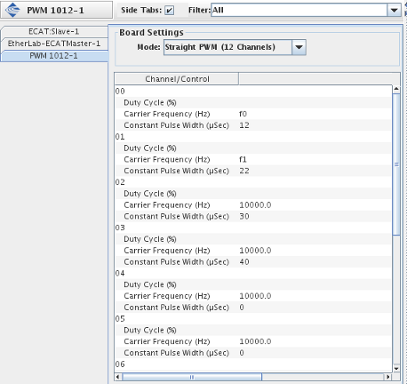
The PWM 1012 is an FPGA-based Pulse Width Modulation (PWM) card from Concurrent. The PWM 1012 autonomously generates TTL pulse width modulated signals with high accuracy. With a timing resolution of 50 ns and the ability to program sine frequencies, carrier frequencies, dead band, and duty cycle in real time makes this card ideal for use in Hardware-in-Loop (HIL) systems.
CS-PWM-1012.
WCS-PWM-1012.
ICS-SWB-1238.
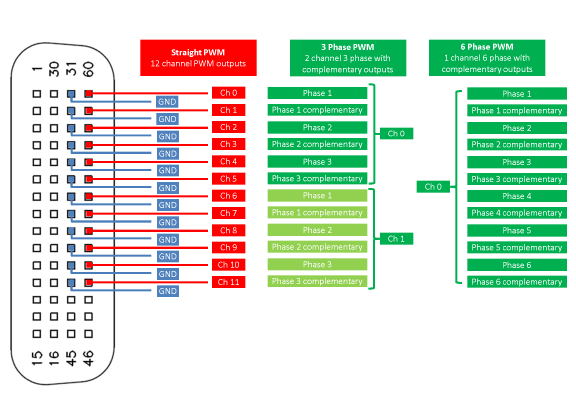
Mode with 12 independent channels, each outputting a stream of pulses at a fixed frequency and duty cycle (duration).

Mode the board will operate in:
Channel or control of a channel. Each control may have an output point mapped to it. Most controls can be set to a constant value when no point is mapped to them.
Value of, or output point mapped to, a control of a channel. Only one or the other will be displayed. Values may be edited by double clicking on them. Mappings are edited via the usual mechanism.
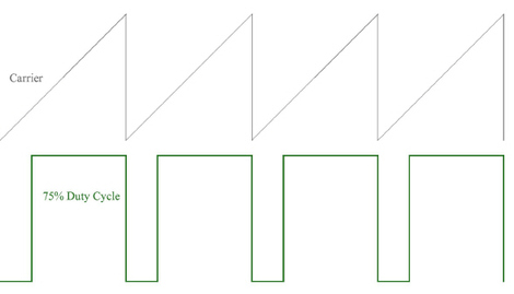
Duration of each pulse as a percentage of the carrier frequency’s cycle time. The valid range is 0 to 100% in 0.1% increments. A point must be mapped to this control for the channel to be active.
The frequency at which pulses are generated. The valid range is 0.01 Hz to 1 MHz. The carrier frequency may be set with a constant or be mapped to an output point.
When this field is non zero, the duty cycle is calculated by the I/O task to maintain the pulse width constant when the frequency is changed.
I.e. duty_cycle = pulse_width X 10-6 X frequency X 100
The constant pulse width is specified in μsec.
Note: When you map the Constant Pulse Width for a channel to an RTDB variable, you must ensure that its value does not result in a duty cycle that exceeds 100%.
Mode with two independent channels. Each channel outputs three pairs modulated pulses at different phases and their complements.
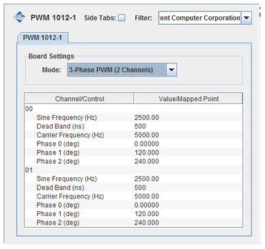
Mode the board will operate in:
Channel or control of a channel. Each control may have an output point mapped to it. Most controls can be set to a constant value when no point is mapped to them.
Value of, or output point mapped to, a control of a channel. Only one or the other will be displayed. Values may be edited by double clicking on them. Mappings are edited via the usual mechanism, by selecting a channel/control on the left side of the I/O Mappings form, then click on a check box for an I/O point on the right side of the form. See I/O Mappings... for details.
Frequency of the sine wave that modulates the duration of the pulses. It must not exceed half the carrier frequency. The sine frequency may be set to a constant or be mapped to an output point.
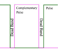
Offset of the beginning and end of the complementary pulse. The valid range is between 50 ns and 10 μs in 50ns increments. The dead band may be set to a constant or be mapped to an output point.
The frequency at which pulses are generated. The valid range is 0.01 Hz to 1 MHz. The carrier frequency may be set with a constant or be mapped to an output point.
The phase of the sine wave modulating the pulse width. There is a separate phase specified for each of the three outputs pairs. The valid range is 0 to 360 degrees. Each phase angle may be set to a constant or be mapped to an output point.
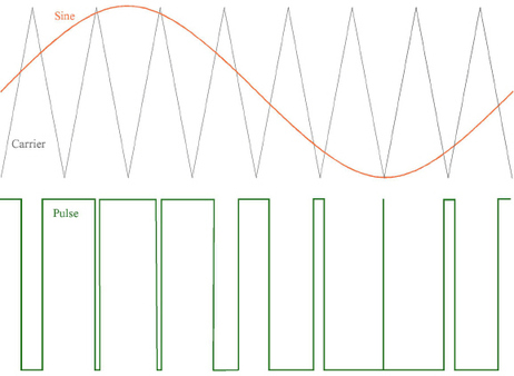
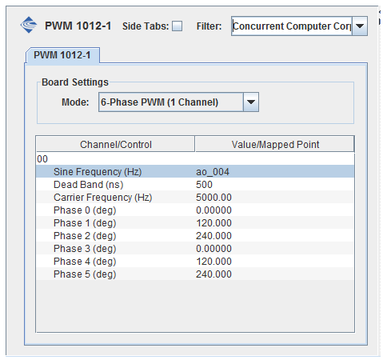
If the sine frequency, dead band, and carrier frequency are set identically in the 3-Phase PWM mode, the PWM 1012 can be treated as a single channel pulse width modulator with six pairs of outputs. Selecting 6-Phase PWM mode conveniently sets those controls on channels 0 and 1 identically.

|
PowerDAQ AO | Resolver:In |

|