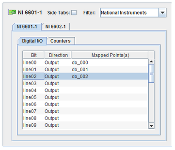
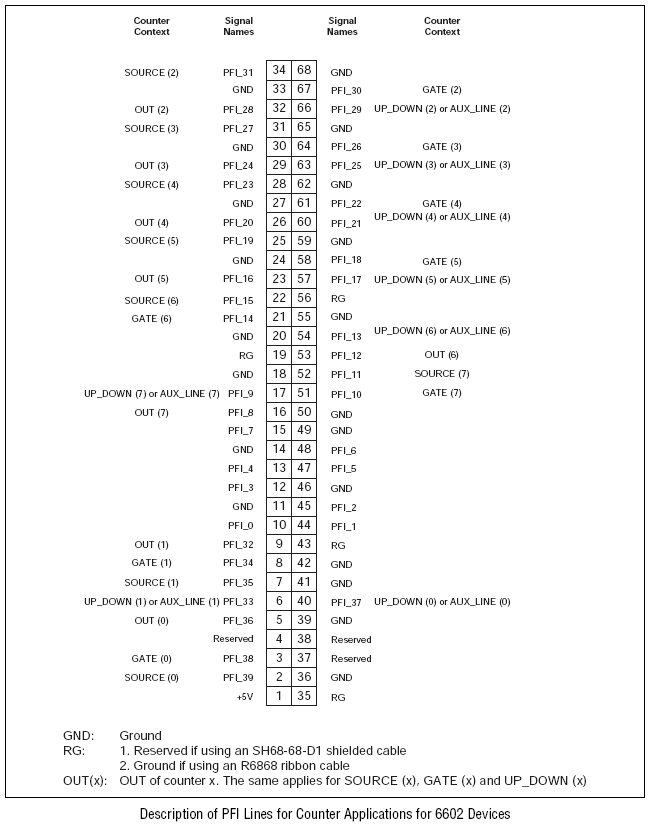
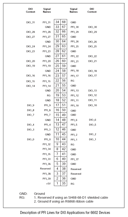
NI 6601 provides four counters/timers and 32 digital I/O channels. NI6602 is similar with eight counters/timers. Pins are shared on the boards between counters and digital channels. Mapping both two I/O points would result in a run-time error.
CS-NI-PCI-6602.
RIQ needed for NI DAQmz.
ICS-SWB-1222.

Digital I/O channel.
Input output direction. Click on a cell and select the direction from the drop-down list. Each digital channel may have its direction set independently.
I/O point(s) a bit is mapped to.
To map a bit to a channel, select a bit on the left side of the I/O Mappings form, then click on a check box for an I/O point on the right side of the form. See I/O Mappings... for details.
Counter designation, and for output counters, controls.
Each output counter has a number of controls that may be set to a default value or mapped to an I/O point. Each input counter may be mapped to an I/O point.
Type of counter the counter is configured as.
For output counters, the default numeric value or output point a parameter of the pulse generator is mapped to. For input counters, the input point the counter is mapped to.
To edit numeric values, double click on the table cell and type in a new value.
To map a point to a output counter’s parameter or an input counter, select a parameter or counter on the left side of the I/O Mappings form, then click on a check box for an I/O point on the right side of the form. See I/O Mappings... for details.
In output Configuration, counters are used as pulse generators. There are three modes, allowing pulses to be specified in three ways.
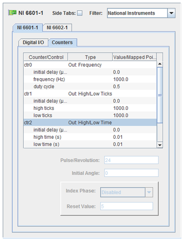
Pulses are specified with a frequency and duty cycle (fraction of the cycle time that the output pin is high).
Pulse are specified with the high and low time as a count of ticks of the 20MHz onboard clock.
Pulses are specified with the high and low time in seconds.
For each of these modes, an I/O point can be mapped to either or both parameters to control the pulses. In the case where one of the parameters is not mapped to an I/O point, a constant value is specified for it.
The initial delay in starting the counter can be specified in microseconds for each output counter.
The counter parameters cannot be updated faster than the cycle that they output. For example, if a test has a frame rate of 1 millisecond and the pulse has a frequency of 50 Hz, the frequency cannot be updated until a pulse cycle (20 milliseconds) after the last update.
In input configurations, counters take measurements of pulses.
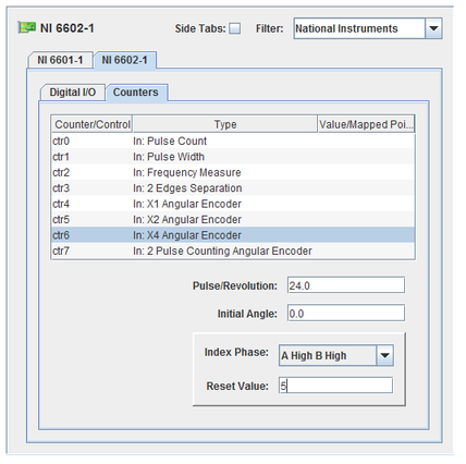
Measures the cumulative Count of pulses.
Measures width of the pulses in seconds.
Measures the frequency of the pulses in Hz.
Measures the time in seconds between edges.
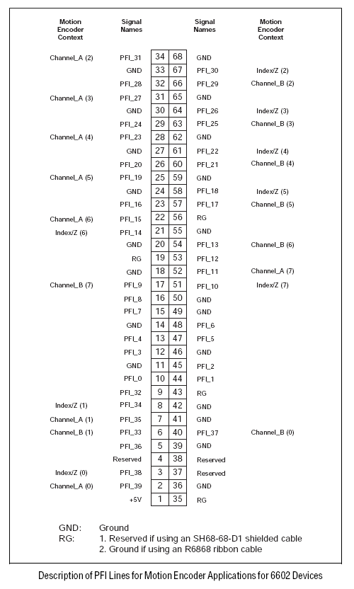
Measure count from quadrature encoder.
Quadrature encoders can have two or three channels: A, B, and sometimes Z. When channel A leads channel B in a quadrature cycle, the counter increments. When channel B leads channel A, the counter decrements. The amount of increments and decrements per cycle depends on the type of encoding (X1, X2, or X4).
Quadrature encoders can also have a Z channel, also referred to as the index channel. A high level on the index channel causes the counter to be reloaded with a specified value in a specified phase of the quadrature cycle. This reload can be programmed to occur in any one of the four phases in a quadrature cycle.
Measure count from a two-pulse encoder.
A pulse on channel A causes the counter to increment on its rising edge. A pulse on channel B causes the counter to decrement on its rising edge.
The angular (quadrature and 2 pulse counting) encoders have a number of paramters that can be set. These parameters appear below the mapping table and apply to the selected counter.
Pulses per revolution.
Initial angle in degrees.
Phase of the encoder that the counter is to be reloaded with the reset value.
Value to reset the counter to when the index channel reaches the specified phase.
Refer to the National Instruments NI660x documentation for more information about the different modes of the input counters.

|
NI6509 | NI 670x |

|