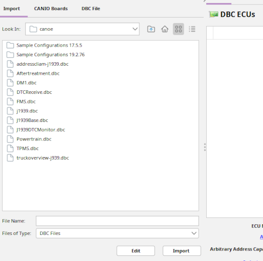
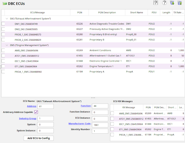
Pick an ECU by clicking on its name and select one or several of the transmit messages.
When an ECU has been selected, the fields below the ECU list will be populated with the specific properties of the ECU.
You can edit the fields to modify for instance the ECU address, industry group,etc.
Labels that are displayed in underlined blue text are clickable and will show possible choices for the field values.
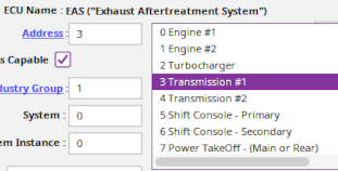 You can either enter a value in the entry field directly or select a value from the list displayed when clicking on the label.
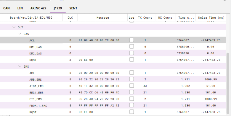
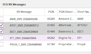 The messages received by the selected ECU are shown to the right of the editable fields. You can also select the message(s) that you want to process
on reception by clicking on the checkbox associated with the message.
The messages received by the selected ECU are shown to the right of the editable fields. You can also select the message(s) that you want to process
on reception by clicking on the checkbox associated with the message.
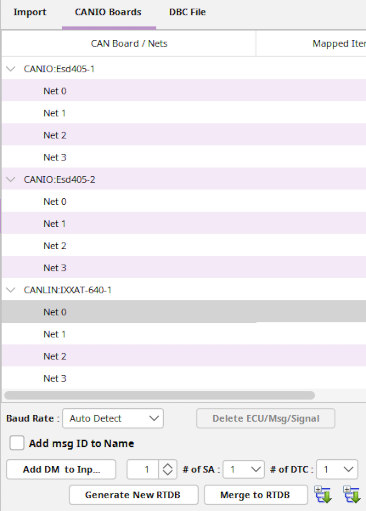 Once you have selected an ECU and the trasnmit and receive messages (PGN's) you want in SimWB, you must select a specific CAN Device/Channel through which the ECU will communicate. as
shown in the picture to the right. Each CAN board instance and its channels are identified by their name.
Once you have selected an ECU and the trasnmit and receive messages (PGN's) you want in SimWB, you must select a specific CAN Device/Channel through which the ECU will communicate. as
shown in the picture to the right. Each CAN board instance and its channels are identified by their name.
After Picking the CAN channel and selecting the ECU and its messages, click on the
 button to add everything to the channel.
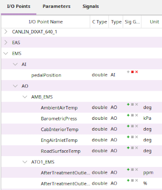
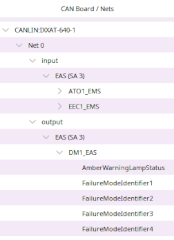 The CAN channel will now be populated with the messages and signals so that the RTDB can now be created.
 The CAN channel Baud rate should also be specified by clicking on the Baud Rate Combo Box. Do not select Auto Detect if the CAN channel is inactive when the SimWB test starts.
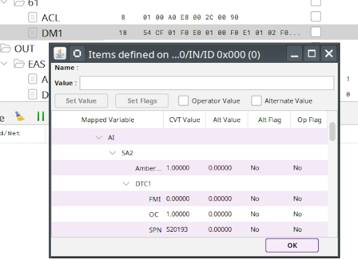
Additionally, you can add Diagnotic Messages (DM's) to an input channel. As a DM is not directly associated with a receiving ECU, A DM message must be added independly to a channel if you want SimWB to receive and process it.
It is impossible to determine ahead of time the length of the DM message - (How many DTC's - Diagnostic Trouble Code) will be sent to SimWB, when adding a DM message, you can specify the maximum number of DTC's it can receive.
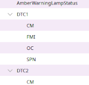 The DTC sub fields (CM, FMI, OC, SPN) will be created for each DTC added to a DM.
It is also not possible to know how many different ECU's (Different Source Addresses SA's) will issue the message, you can also create slots in the mapping so that the same DM message DM1,DM2,etc. can be receive from multiple ECU's.
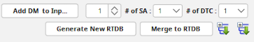 All this can be specified in the DM sub-panel at the bottom of the CAN channel display.