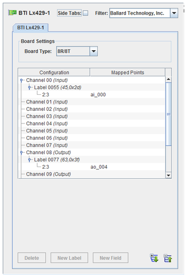

Labeled messages are sent or received over each channel. I/O points are mapped to fields within these messages.
CS-DD-42916I3-300.
WCS-DD-42916I3.
ICS-SWB-1211.

Expands the hierarchy tree showing board configuration.

Collapses the hierarchy tree showing the board configuration to show only the channel nodes.

Adds a new message label for the selected channel.

Adds a field to the selected label.

Deletes the selected node and everything, including mappings, below it. The top level nodes cannot be deleted.
Selects which type of BTI Lx429 is installed on the system. This setting determines the number of channels and whether they are input or output channels. Changing this setting will remove existing mappings to this board.

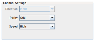
Selects the I/O direction of the channel. This setting is not editable, but is determined by the board type.
Selects the parity of the channel.
Selects the speed of the channel.
100 kbits/s.
10 kbits/s.

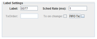
Unique identifier for a message on this channel. Usually specified as an octal number.
Rate at which messages are sent (output channels only).
Specifies that messages are sent via FIFO instead of scheduled rate (output channels only).
Specifies that message are sent when a value changes (FIFO Tx only).
The priority to send the label when multiple labels are output at the same time on the same channel (FIFO Tx only).

Bit offset and size of the field. Only integer bit fields are supported. Single-bit fields are mapped to digital points. Multi-bit fields are mapped to analog points.
Specifies that bits 3 through 22 are interpreted as a BCD value.
Specifies that bits 1 through 2 are interpreted as an integer value.
I/O point(s) a field is mapped to.
To map a point to a field, select a field on the left side of the I/O Mappings form, then click on a check box for an I/O point on the right side of the form. See I/O Mappings... for details.
The process computes all 32-bit output words corresponding to output items and places them into the output FIFO. BTI Lx429 words that are unchanged since the last test cycle will not be queued.
The FIFO is read by the btilx429asyncio asynchronous task that writes them to the hardware board.
This process runs asynchronous to the simulation loop and handles both inputs from and outputs to the BTI Lx429 boards. Due to the fact that a BTI Lx429 board can only be opened by one task at a time and a single board can be configured to do inputs and outputs simultaneously, this process is multithreaded.
There is a separate thread for each board that is configured as input (that is, at least one channel on the board is configured for input and at least one RTDB variable is mapped to that channel.) The input thread configures the board to notify itself of any new inputs received via a software interrupt. The thread sleeps until the interrupt wakes it. It then reads the interrupted channel immediately and queues an update request into the asyncio FIFO queue. In this mode, the input thread does not poll the board to detect new inputs.
There is a separate thread for each board that is configured as output (that is, at least one channel on the board is configured for output and at least one RTDB variable is mapped to that channel.) The output thread polls the output FIFO at a regular interval. The default interval is every 5 milliseconds and can be specified as a command line argument with –t msec in the options column of the I/O Tasks form.

|
Baby LIN | CAN DBC Import |

|