
This example shows the workflow for switching between SIL and HIL components in a test. This example highlights a Simulink®-based workflow, but the principles can be easily extended for other modeling enviroments.
Rapid prototyping of a system involves multiple iterations, with frequent modifications of software and hardware models. For instance, consider the following system configuration, where we start with software models of a plant and controller. The goal is to design a plant and controller such that the performance meets specified requirements. During the design process, different versions of the plant and controller models are tested. The design process can include switching between a software model (software-in-the-loop, also referred to as SIL) and a hardware model (hardware-in-the-loop, also referred to as HIL) of the plant and/or controller. SimWB allows you to seamlessly move between SIL and HIL configurations for a given test.

Suppose you are testing the response of a plant to stimulus. This stimulus can be generated either via a software-based wave generator (SIL) or an actual wave generator device (HIL).
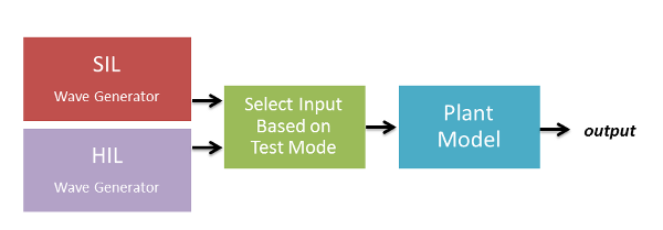
This example uses a plant model with x as input and y as output (plant_model subsystem in the following Simulink model). Suppose you want to switch the source of x based on whether you are performing a SIL test or a HIL test.
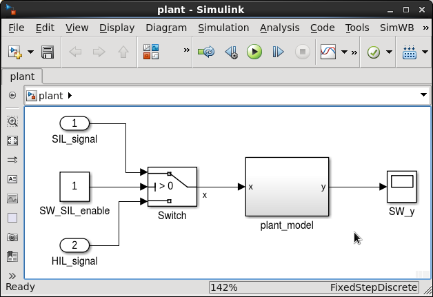
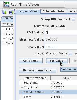
Use a Switch block to change input sources. Configure both inputs to the switch (SIL_signal and HIL_signal) and the the switch control (SW_SIL_enable) to be RTDB (input) variables. When SW_SIL_enable is 1, the SIL wave generator is used. Conversely, when SW_SIL_enable is 0, the HIL wave generator is used. You can vary the value of SW_SIL_enable in SimWB when a test is running using the Real-Time Viewer (RT-Viewer) or specify an initial value before the test is run.
The SIL stimulus is generated by the the SIL_signal_generator model, configured as follows:
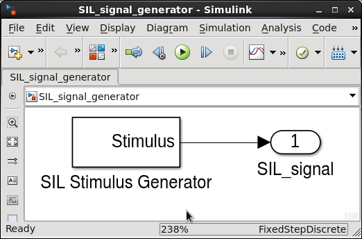
Note that the signal name of the SIL signal generator output is the same as the SIL input used in the plant model. When you generate the RTDB for these two models, use the nonhierarchical option so that the SIL_signal is designated as an AIO. AIOs are safe to use within a single test frame, when the source/destination model dependencies are declared in the test definition. (See Figure 6).
Suppose the RTDB variables for the SIL wave generator, HIL wave generator, and plant model are as follows:
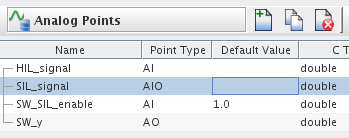
Here, HIL_signal is an analog input (AI) that is mapped to an input device, such as the AD3224 DS. SIL_signal is the output of the SIL wave generator model. HIL_signal and SIL_signal are also inputs of the plant model. SW_SIL_enable is the plant input switch control and SW_y is the plant output.
Finally, configure the test as follows:
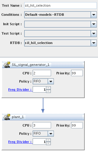
There is a data dependency of the plant model on the SIL signal generator for the value of SIL_signal. This dependency is enforced as part of the test configuration (vertical arrow). So, within a test frame, the SIL_signal_generator model first writes a value to SIL_signal, which is then read by the plant model. Without the declaration of the data dependency, the write to SIL_signal could possibly occur after the read from SIL_signal.
When you run a session of the test configured above, you can easily switch between the HIL- and SIL-wave generators by changing the value of SW_SIL_enable RTDB variable.
You can use multiple approaches to program the logic to switch between components based on the value of an RTDB variable. These include using: