This example shows how to generate SimWB-compliant code for a Simulink® model that uses bus signals. You can map source/sink blocks that use non-virtual buses to the RTDB and access each element of the bus in SimWB. SimWB supports this feature in MATLAB® R2010b and later releases.
In this example, the model ccur_bus_test_in outputs a non-virtual bus signal. This same bus signal is the input in the model ccur_bus_test_out, which decomposes the bus into its basic elements. You can generate code for both these models and create a test that includes both these models. When you run the test in real time, you observe that changes in a source value in the ccur_bus_test_in are propagated to the corresponding sink in ccur_bus_test_out.
For information about non-virtual bus signals, refer to the MathWorks documentation.
The models ccur_bus_test_in and ccur_bus_test_out are located in the $simwbroot$/examples folder.
Open these models by typing ccur_bus_test_in and ccur_bus_test_out at the MATLAB command prompt.
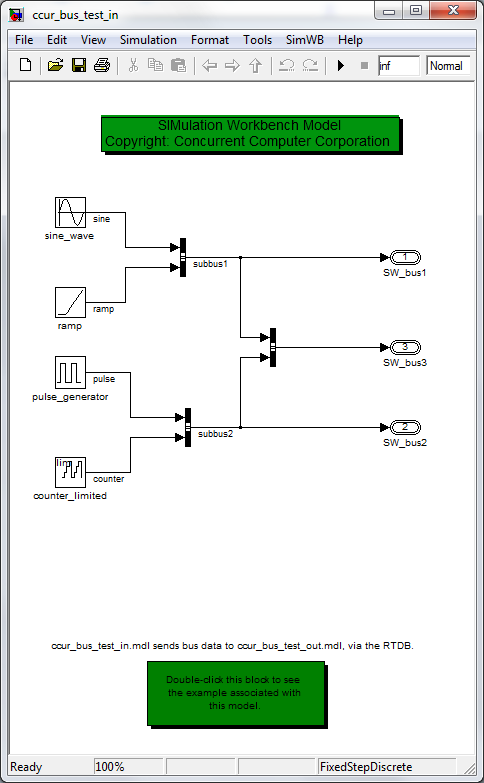
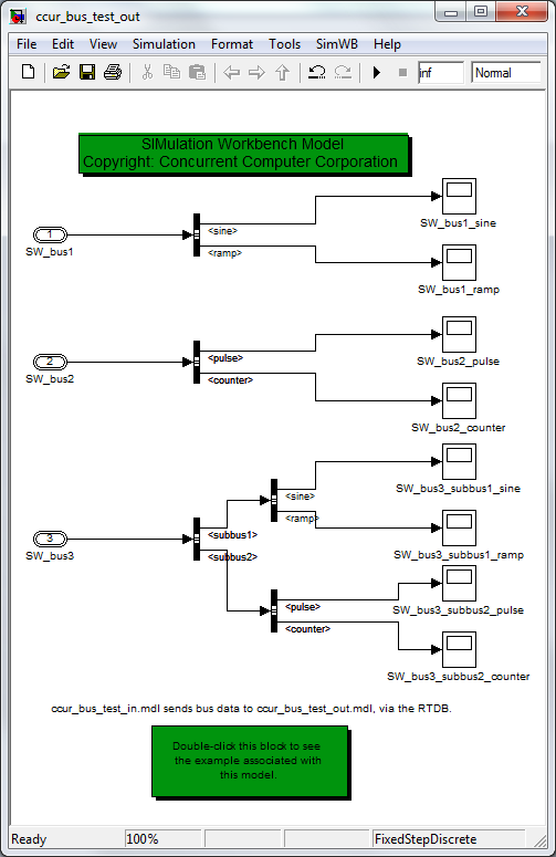
Notice that the outputs in ccur_bus_test_in, connected to the model buses, are named as inputs in ccur_bus_test_out. When you generate code for these models and execute them in a single SimWB test, you effectively connect the sinks in ccur_bus_test_in to the sources in ccur_bus_test_out, via the bus signals.
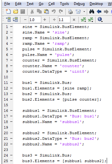
The buses in these models are created using the script ccur_bus_test_setup.m.
This script is loaded in the model initialization callback, InitFcn, for both models.
To view the contents of this file, type edit ccur_bus_test_setup at the MATLAB command prompt.
Instead of using a script to generate or modify bus objects, you can also use the buseditor.
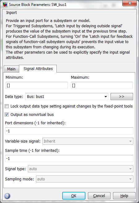
To specify an input/output as a nonvirtual bus port, open the port block dialog. Click the Signal Attributes tab and execute the following steps:
Bus: bus1.
Note that the prefix 'Bus: ' is required when specifying a nested bus.
To visually verify that a signal is interpreted by Simulink as a non-virtual bus,
update your model (Ctrl + D). The signal line should appear thickened, as shown in the model images above.
Because the two models share signals, before generating code using the MLToolkit GUI, you must modify the SimWB preferences. In the Simulink editor, select SimWB > Preferences. The SIMulation Workbench Preferences GUI opens. In the RTDB tab:
modelname.subsystem. Instead, the variable name will be the
sink/source block name.
So, ccur_bus_test_in and ccur_bus_test_out will contain variables in common.
For example, SW_bus1, SW_bus2, and SW_bus3.
Note that AIO/DIO/STRIO variables cannot be logged consistently.
Following the workflow described in Generate Code for Simulink Model Using MLToolkit, generate SimWB-Compliant Code for ccur_bus_test_in. Load the code to an RTDB named ccur_bus. For theCreate RTDB Variables option, use the default settings, which will create RTDB variables for all source/sink blocks with the SW prefix.
Next, generate code for ccur_bus_test_out and load it to the same RTDB, ccur_bus. Similar to ccur_bus_test_in, when you create the RTDB variables, use the default settings for the Create RTDB Variables option. When you click Create and Upload RTDB, the RTDB Append/Overwrite dialog appears. Click Append/Update.
The signal.db file on the SimWB host machine (located in the relevant RTDB folder) shows that the elements of the buses have the AIO point type. This point type is derived based on how the signals are used in both models. However, the signal.db file on the local machine (located in the current MATLAB work directory) does not reflect the overall point type for these signals. Rather, it reflects the point type for the signals as relevant to the last model used by the MLToolkit GUI, ccur_bus_test_out.
Now that you have appended the RTDB and generated code for ccur_bus_test_out, you must regenerate the code for the first model, ccur_test_bus_in. Regenerating the code ensures that it uses the latest signal point types.
Open the Simulation Workbench Control Center on your local machine. Load the ccur_bus RTDB. To inspect its signals, in the editor menu, select RTDB & I/O > Analog Points.
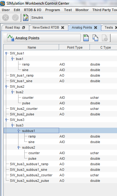
Notice that all the bus signals are of the AIO point type. All source signals from ccur_bus_test_in are AI points, and all sink signals from ccur_bus_test_out are AO points.
Create a test for the ccur_bus RTDB.
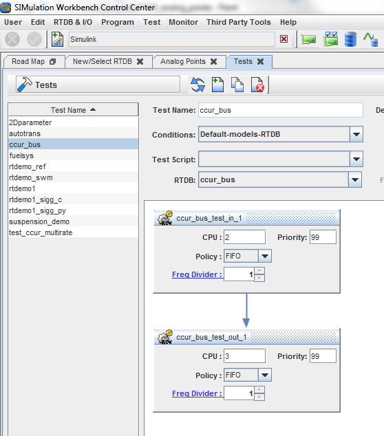
Run a session of this test.
Add all the variables to the Real-Time Viewer table.
Change the value of a source, for example, the sine wave.
You observe that the bus1 element, sine, and bus3 sub-element, sine,
reflect the new value, as do the associated scopes.
Similarly, test that changes to the other sources are propagated by the related buses and scopes.
createMex function.
This function creates the MEX files for these S-functions and
places them in the appropriate location.
This function requires you to select the right compiler in MATLAB using
mex -setup beforehand.
To find the right compiler,
refer to the MathWorks compiler selection table.