Generate Code for Simulink Model Using MLToolkit
This example shows how to generate code for a Simulink® model using the MLToolkit.
The MLToolkit allows you to easily generate SimWB-compliant code from a Simulink model. It provides you the convenience of generating this code without modifying the Simulink model to include hardware-specific S-Function blocks. Instead, the software automatically inserts RTBD-access-specific blocks during code generation. Use the generated code to simulate the model in real time using SimWB, which supports a wide variety of I/Os for model simulation.
Contents
Prerequisites
Install SimWB and MLToolkit
This example requires the MLToolkit and SimWB Real-Time core.
To confirm that this software is installed, open any Simulink®model.
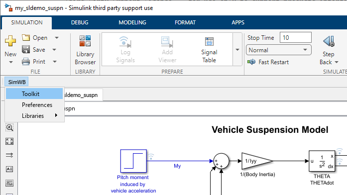
The SimWB option must be visible in the menu bar.
For MATLAB® versions R2019a and earlier:

For MATLAB® versions R2019b and later:
Start Configuration Server Process
Before using the MLToolkit, you must start the Real-Time core process, cfgsrv, on the real-time host. The cfgsrv process is an interface required to configure, set up, and run a Simulink model in real time. For more information about this process, see Configuration Server (cfgsrv).
Automotive Suspension Model
This example uses a copy of the
sldemo_suspn Simulink® model, which describes the suspension of an automotive.
For more information about this model,
see Automotive Suspension
in Simulink documentation.
Open the model.
Type sldemo_suspn at the MATLAB command prompt.
Create a copy of this model. Save this copy model as
my_sldemo_suspn.mdl.
The remainder of this tutorial will use the copy model. So, close the
sldemo_suspn model, and open the copy,
my_sldemo_suspn, instead.
Specify Fixed-Step Solver for Model
To generate code for a Simulink® model, it must use a fixed-step solver.
To specify a fixed-step solver in the Simulink editor, click
Simulation > Model Configuration Parameters.
In the Select pane (left-hand side) of the Configuration Parameters dialog box, select Solver.
In the Solver Options pane (right-hand side), select Fixed-step in the Type menu.
In the Fixed-step size box, enter 0.01.
Step 1: Prepare Signals of Interest in Simulink® Model
To access signals in a Simulink model in real time using external hardware, ensure that these signals are connected to source (inputs) or sink (outputs) blocks. These blocks are mapped to RTDB inputs/outputs.
If necessary, add the relevant blocks to the model. Specify names for these source/sink blocks that are valid C variable names. Block names that contain spaces cannot be included in the real-time database. So, you must eliminate spaces from the names of blocks of interest.
For example, consider the following signals:
Input Signals
-
My, originating at thePitch moment induced by vehicle accelerationblock. The source block name contains spaces. To use an external device to supply this signal during real-time simulation, you must rename this block to eliminate the space. For example, rename the block tolong_moment. Similarly, to access thehsignal, which originates at theRoad Heightblock, you must rename the block toroad_height.
-
Signal originating at the
acceleration due to gravityblock. Because the source block name contains spaces, the MLToolkit will not map this signal to the RTDB. So, you cannot modify this signal during real-time simulation.
Output Signals
-
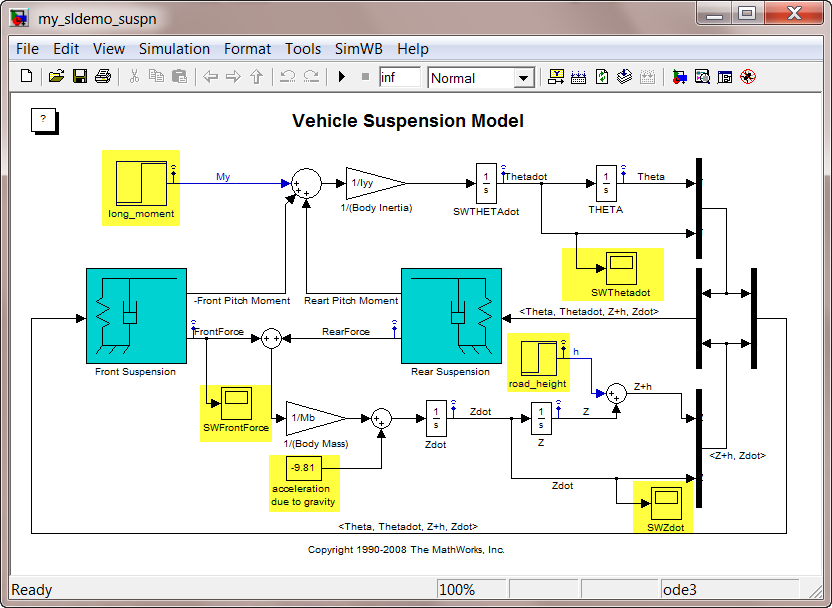
Thetadot, originating at theTHETAdotblock. To use an external device to log this signal, you must add an RTDB-supported sink block to this signal. Add a Scope block namedSWThetadotto this signal. Instead of the Scope block, you can also use the Outport, ToFile, ToWorkspace, and Display blocks. For this example, use scope blocks for output signals. -
FrontForce, originating at theFront Suspensionblock. Add a Scope block namedSWFrontForceto this signal. -
Zdot, originating at theZdotblock. Add a Scope block namedSWZdotto this signal.
The modified model is as follows:
Step 2: Connect Model to Real-Time Host
Open the MLToolkit GUI. In the menu bar of the Simulink Editor for the model, click SimWB > Toolkit.
In the Simulator Access tab, specify the following:
- Host Name - Name of the real-time host or IP address of the computer running the cfgsrv process (for example, 192.168.0.1)
- Username, Password - Name and password of authorized user of RTDB
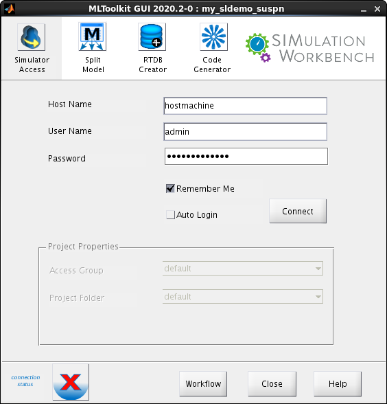
Click Connect.
When the model connects to the real-time host successfully, the connection icon status changes as follows:

In the Project Properties pane, use the default values for Access Group and Project Folder.
Step 3: Create RTDB for Simulink Model
Click theRTDB Creator tab. Specify the following:
- Create RTDB Variables - Select the Using Regular Expressions in Block Names check box. Use the default values for the boxes that specify the regular expression values for the source and sink names.
-
RTDB - Enter
my_sldemo_suspn. Typically, you specify the model or project name in this field.
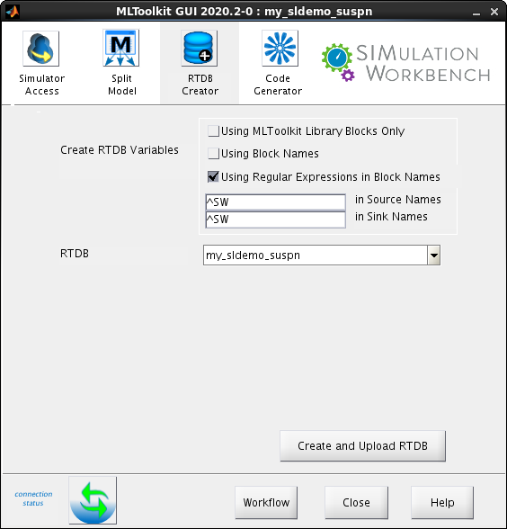
Click Create and Upload RTDB. The RTDB Append/Overwrite dialog box opens.
Click Overwrite. This option overwrites any existing RTDB on the real-time host that has the same name as specified in the RTDB box.
A text file, signal.db, is created in the current folder. This file contains the RTDB variable definitions. The software uploads this file to the real-time host. So, when you use the SIMulation Workbench Control Center after generating the code, this model is available in the GUI.
Step 4: Generate SimWB-Compliant Code
Click theCode Generator tab. Specify the following:
- Map Blocks to RTDB Variables - Use the same options as in the RTDB Creator tab in step 3.
-
RTDB - Select
my_sldemo_suspnfrom the list. This is the RTDB name specified in the RTDB Creator tab in step 3. Ifmy_sldemo_suspnis not available in the list, the RTDB creation was unsuccessful. -
Compiler Options - Use the default value,
-g. - Linker Options - Use the default value, an empty string.
- Make Only - Use the default option, unselect this check box.
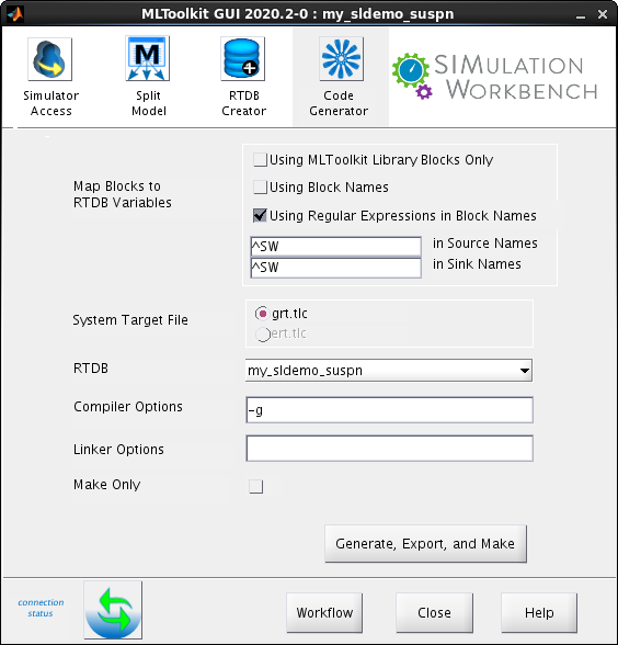
Click Generate, Export, and Make. The software generates SimWB-compliant code and a real-time executable, and uploads the same to the real-time host. The following image shows a snippet of the generated output.

The software checks if the model is compliant with the selected RTDB before it generates SimWB-compliant code. The check ensures that source and sink blocks in the model uniquely map to variables in the RTDB. A block maps to an RTDB variable when they have the same name, data type, and dimension. The model must pass the compliance check for code generation.
| Note: You cannot use the Simulink Coder keyboard shortcut, Ctrl + B, to generate SimWB-compliant code. You can use only the MLToolkit GUI to generate this code. |
Step 5: Launch SIMulation Workbench Control Center
Launch the SIMulation Workbench Control Center. Use this tool to set up tests, configure the RTDB, run/playback the model, and create custom HMIs for testing the model.