NET Stream I/O
The NET Stream I/O device supports sending and receiving messages over a network.
It is similar in functionality to the original NET I/O but it allows bidirectional communication on the same socket.
Reference Information
I/O Card Model Number
N/A
I/O Driver Model Number
N.A
I/O Module License:
ICS-SWB-1240
In contrast to the NET I/O device where the basic communication link is a message, here the basic communication link is a stream.
A stream defines the 2 end points of the link via IP/Port combination and client or server configuration.
-
A client link must define the target IP and destination so the connection can be established. Optionally, the source from where the connection originates can be specified.
-
A server link must define the IP port that the remote client must connect to to establish the communication.
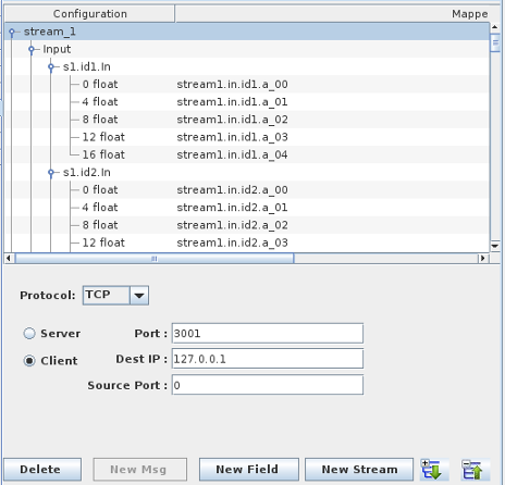
Once a stream has been created, input and output messages can be created. A message is the payload where RTDB items can be mapped.
Multiple streams can be defined on the same NET I/O Stream devices provided they do not use conflicting combination of IP addresses / IP Port.
Buttons
Expand All
Expands the hierarchy tree showing message and mapping information.
| 
|
Collapse All
Collapses the hierarchy tree showing the message information.
|
 |
New Stream
Adds a new stream to the NET I/O Stream device.
|  |
New Msg
Adds a new message to the selected input/output branch under the specified stream.
|  |
New Field
Adds a mappable field to the selected message.
|  |
Delete
Deletes the selected node and everything, including mappings, below it.
|  |
Streams
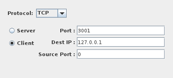
Protocol
Network protocol used to send or receive the message.
TCP UDP
Type
Whether the link is client or server.
Server: The I/O task will listen for incoming connection on the specified IP port.
Client: The I/O task will connect to the specified IP address/ host name on the specified port.
Port
For a server link, this is the port number to listen on for incoming connection.
For a client link, this is the port number that we are connecting to.
Dest IP
For a server link, this is disabled as we will accept connection on any ethernet interface on the system.
For a client link, this is the IP or the system name to connect to.
Source Port
This is only visible for client link. It is optional (default 0 means the port is selected by the OS). Otherwise , the connection to the remote server will originate from this port.
Messages
Message Name
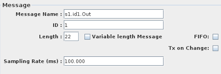
Unique name for this message.
ID
Sixteen bit identifier for this message. The message identifier is transmitted in the first two bytes of the message. if The identifier is specified as -1, the message is transmitted
without the header id word. The identifier must be unique across messages defined with the same source/destination port.
Using an identifier as header to the message, several messages with different I/O mapping can be sent/received on the same IP Port/Address combination.
Length
Length of the message in bytes. This includes the two-byte message identifier.
Variable length message
When this is selected, the length of the message is determined by the length of the string variable mapped to it.
For input messages, the length of the message
received on the specified port defines the length of the input string variable mapped to the message.
Note: This option will restrict you to mapping a single string type variable to the message.
Therefore, if you turn the option on a message that already contains mappings, all the mappings will be lost. Only the first mapping will be conserved if
the raw type of the mapping is string .
When this option is on, the message ID and the Length fields are disables in the message definition panel.
You will only be able to create a single string type mapping for the message.
ASCII/Binary buffer
This option enables you to send/receive binary as well as ASCII data. The length of the buffer to transmit is determined by the length of the mapped string variable
regardless of the content type.
If you receive binary content in the string variable, you will have to write a SimWB script or user model to parse the content of the string.
Remember that you can view the binary content of a string variable in the RTViewer by selecting the "String URL Encoded" check box in the panel.
|
Sampling Rate
Period, in milliseconds, at which the transmit message will be sent. The period can be specified in sub millisecond as 0.5, 0.25 or 0.125. Sub
millisecond rates are rounded down to one of those three.
FIFO
When set , do not send this message at regular interval defined by the sample rate but only when needed.
If Tx on Change is set, the message will be sent whenever the content of the message changes. Otherwise it will be sent only when
the user requests transmission via a SimWB API call - usually called by a test script or a user model.
Tx on Change
This only applies when the message is sent in FIFO and not on a schedule via a sample rate. See above.
Mappings
I/O points are mapped to specific fields of messages. Single-bit Packed fields can only be mapped to digital points. All other fields can only be mapped to analog points.
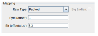
Raw Type
Specifies how to interpret the raw bits of the message field.
Packed
Integer bit field, specified with a byte offset to a 32-bit integer and a bit offset and size within that 32-bit field. Single bit fields are mapped to digital points, all others to analog points.
char
One-byte integer field, specified with a byte offset. Integer fields are mapped to analog points.
short
Two-byte integer field, specified with a byte offset. Integer fields are mapped to analog points.
int
Four-byte integer field, specified with a byte offset. Integer fields are mapped to analog points.
long long
Eight-byte integer field, specified with a byte offset. Integer fields are mapped to analog points. Values greater than 253 may be transmitted with some imprecision.
float
Four-byte floating point field, specified with a byte offset. Floating-point fields are mapped to analog points.
double
Eight-byte floating point field, specified with a byte offset. Floating-point fields are mapped to analog points.
Byte (offset)
Field’s offset in the message in bytes. These are data offsets only, i.e. the first offset is ALWAYS zero. Do NOT include the 2-byte ID when present. For Packed, this is the offset of the 4-byte integer containing a bit field.
Bit (offset:size)
Bit offset and size of a Packed field within a 4-byte integer block. Bits are numbered from the high order bit of the 4-byte block. Which byte this bit is in is determined by the Big Endian setting. The offset is measured from the high order bit of the block to the high order bit of the field.
Big Endian
Interprets values as most significant byte first. This is the reverse of the default way data is handled on Intel x86 platforms.
String Length
Used only for the input mappings. Use this to set the expected string length of incoming message. If this is set to '0', SimWB will assumes the incoming string is NULL terminated and try to read till the end.
Message Control
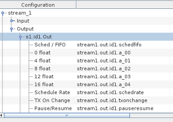
When creating a NETStream IO output message , message control branches are automatically added. Those mappable controls are in addition and do not replace the SimWB API calls with the same
functionality. By mapping message control to RTDB variables, the model(s) - which have no direct access to the SimWB API - can directly control the CAN messages properties.
When mapping the Sched / FIFO , Schedule Rate,etc. branches to RTDB variables, the output message properties can be controlled directly by changing RTDB variable values. The values
of the connected variables are initialized to value corresponding to the properties of the messages. Thus, the value of the variables defined in the initial conditions
or the default value assigned when creating the RTDB variables do not apply.
- Sched / FIFO : When 1 , the message is in scheduled mode and the message is sent at the period defined by the Sched Rate field. When 0, the message is in FIFO mode.
- Schedule Rate : This the period in milli seconds at which the message is sent when in schedule mode.
- Pause / Resume : When 1, the message is paused. Set to 0 to resumes.
- TX On Change : This only apply when the message is in FIFO mode. When set to 1, the message is sent whenever the content of the CAN frame changes. When set t0
0, the message is not sent unless the TX Now value is set.
- TX Now: When the message is in FIFO mode and TX on change is set to 0, the message is only sent whenever TX Now is set. As long as the TX Now is set to != 0, the message is sent
at every frame
Mapping Table
Configuration Column
Configuration tree.
Mapped Point(s) Column
I/O point(s) a field is mapped to.
To map a field to a channel, select a field on the left side of the I/O Mappings form, then click on a check box for an I/O point on the right side of the form. See I/O Mappings... for details.

