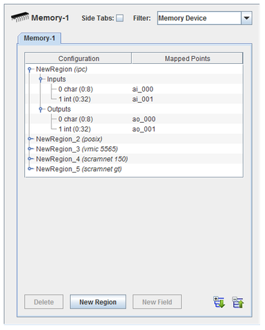
I/O points may be mapped to shared memory regions. Each memory “device” has an instance of the memin and memout I/O tasks. Multiple regions of different kinds can be defined in each “device”.


Expands the hierarchy tree showing board configuration.

Collapses the hierarchy tree showing the board configuration to show only the channel nodes.

Adds a field to the selected shared memory region.

Adds a shared memory region definition.

Deletes the selected node and everything, including mappings, below it. The top level nodes cannot be deleted.
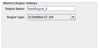
 To configure a new shared memory region, click on the New Region button. When a region is selected, one of the settings dialogs below appears below the mapping table. Each dialog has the following settings:
Unique name of the region.
Type of shared memory region
Only one region specification is supported for a VMIC 5565 Reflective Memory card.
Only one region specification is supported for a SCRAMNet GT 200 Memory card.
Below those settings are settings specific to the region type.
System V shared memory. The memory region must already exist in order to be used by SIMulation Workbench. SimWB will not create the region and will fail to initialize if the region does not already exist. These regions are assumed to be interfaces into other applications, so those applications are responsible for creating them.
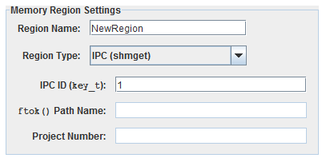
Shared memory key. To calculate the key instead of giving it directly, clear this field to enable the following two fields to provide the path name and project number properties to the ftok() function.
Path to an existing file used by ftok() to calculate the IPC ID.
Project number used by ftok() to calculate the IPC ID.
POSIX shared memory segment. The memory region must already exist in order to be used by SIMulation Workbench. SimWB will not create the region and will fail to initialize if the region does not already exist. These regions are assumed to be interfaces into other applications, so those applications are responsible for creating them.
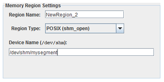
Path to an entry in the /dev/shm file system that will be passed to the shm_open() call.
Physical device that replicates its contents to other nodes connected to it.
CS-VMIPCI-5565-xxx.
WCS-VMIPCI-5565
ICS-SWB-1223
CS-GE-PCI-5565-x.
WCS-GE-PCI-5565
ICS-SWB-1223
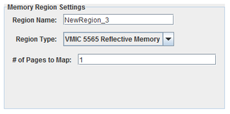
Number of 4096-byte pages to access on the board.
Physical device that replicates its contents to other boards connected to it. There are no additional configuration parameters associated with this board. The I/O tasks will map the entire board memory.
CS-SYS-DPCIG0xM-20, CS-SYS-DPMC0xM-20.
N/A
ICS-SWB-1223
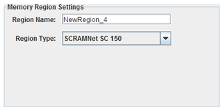
Physical device that replicates its contents to other boards connected to it. There are no additional configuration parameters associated with this board. The I/O tasks will map the entire board memory.
CS-SYS-GPCI-20.
WCS-SYS-GPCI
ICS-SWB-1223
 To create a new field, select a memory region and click on the New Field button.
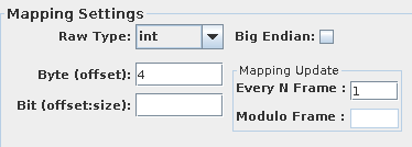
I/O points are mapped to specific fields of messages. All fields are specified with a byte offset into the shared memory region. Integer types can have an optional bit offset and size to specify bit field with the integer at that byte offset.
Single-bit integer fields can only be mapped to digital points. All other fields can only be mapped to analog points.
Specifies how to interpret the raw bits of the message field.
One-byte integer field.
Two-byte integer field.
Four-byte integer field.
Eight-byte integer field.
Four-byte floating point field.
Eight-byte floating point field.
Fixed-length string field. String length is set to the length of the default value of mapped RTDB variable.
Field’s offset in the shared memory region in bytes.
Bit offset and size of a bit field within an integer. Leave blank to specify the entire integer. Bits are numbered from the high order bit of the 1-, 2-, 4-, or 8-byte block of the selected raw integer type. Which byte this bit is in is determined by the Big Endian setting. The offset is measured from the high order bit of the block to the high order bit of the field.
Interprets values as most significant byte first. This is the reverse of the default way data is handled on Intel x86 platforms.
To map a field to an I/O point, select a field on the left side of the I/O Mappings form, then click on a check box for an I/O point on the right side of the form. See I/O Mappings... for details.
Configuration tree.
I/O point(s) a field is mapped to.
To map a field to a channel, select a field on the left side of the I/O Mappings form, then click on a check box for an I/O point on the right side of the form. See I/O Mappings... for details.