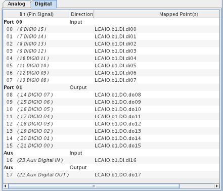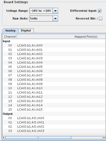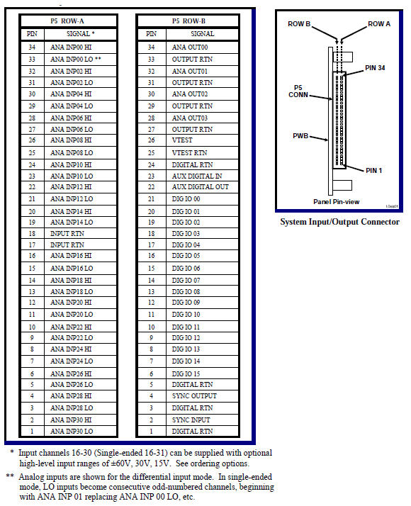
The General Standards LCAIO is a multi-function board providing 16 analog inputs channels, 4 analog output channels, and 18 digital I/O lines.
CS-GS-16AIO-41.
WCS-16AIO.
ICS-SWB-1213.

Selects the voltage range for all the channels on the board.
The raw units used by SIMulation Workbench can be configured as either Raw Count or Volt. This is the unit used to store the raw value in the SimWB RTDB for the mapped item.
When Volt is selected, the voltage read from the board is stored as the raw value in the RTDB. If your I/O point is defined with an associated engineering conversion, you must write the conversion to convert from volt to engineering unit. Without engineering conversion, the item value and raw value in the RTDB will be the same and expressed in volts.
When count is selected, the unsigned 16-bit integer value read from the board is stored as the raw value. If your I/O point is defined with an associated engineering conversion, you must taken into account that the raw value range of 0 to 0xffff corresponds to the voltage range configured on the board.
Selects whether the inputs are configured as 32 single ended channels or 16 differential mode channels.
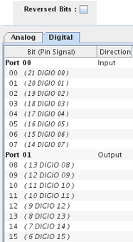
Reverse the LCAIO connector bit notation. This only applies to the digital I/O. The original implementation of the LCAIO I/O task reversed the bits from their actual location on the connector. When this is on (the default for RTDBs created prior to this option being available) the bits are reversed on the connector.
Mappings for the analog channels.
Analog channels that I/O points may be mapped to. Note that there are separate input and output channels indented under the appropriate label.
Points the channel is mapped to.
Select a channel on the left side of the I/O Mappings form, then click on a check box for an I/O point on the right side of the form. See I/O Mappings... for details.
Mappings for the digital channels.
Digital channels that I/O points may be mapped to. The digital channels are grouped into two ports of eight channels plus an additional two auxiliary channels. The I/O direction of the ports is selectable. The I/O direction of the auxiliary channels is fixed by the LCAIO hardware and is not selectable.
Shows the I/O direction of the ports and auxiliary channels and selects the direction of the ports.
To change the I/O direction of a port, click on the table cell with the current direction and select a new direction from the drop down menu. If the I/O direction is changed, any I/O point mappings to any of the eight digital channels on that port are removed.
The I/O direction of the auxiliary digital channels cannot be changed.
Points the channel is mapped to.
Select a bit on the left side of the I/O Mappings form, then click on a check box for an I/O point on the right side of the form. See I/O Mappings... for details.
When Reversed Bits is not selected. The mapping dialog for the digital points appears as follows: |

|
