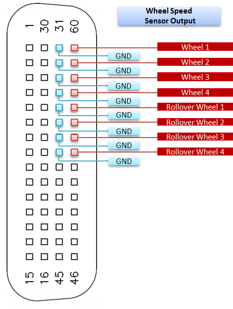
| Pin | Pin Name | Function | Pin | Pin Name | Function | Pin | Pin Name | Function | Pin | Pin Name | Function |
| 1 | NC | - | 16 | NC | - | 31 | GND | GND | 46 | NC | - |
| 2 | NC | - | 17 | NC | - | 32 | GND | GND | 47 | NC | - |
| 3 | NC | - | 18 | NC | - | 33 | GND | GND | 48 | NC | - |
| 4 | NC | - | 19 | NC | - | 34 | GND | GND | 49 | NC | - |
| 5 | NC | - | 20 | NC | - | 35 | GND | GND | 50 | NC | - |
| 6 | NC | - | 21 | NC | - | 36 | GND | GND | 51 | NC | - |
| 7 | NC | - | 22 | NC | - | 37 | GND | GND | 52 | NC | - |
| 8 | NC | - | 23 | NC | - | 38 | GND | GND | 53 | OUT7 | Rollover 4 |
| 9 | NC | - | 24 | NC | - | 39 | NC | - | 54 | OUT6 | Rollover 3 |
| 10 | NC | - | 25 | NC | - | 40 | NC | - | 55 | OUT5 | Rollover 2 |
| 11 | NC | - | 26 | NC | - | 41 | NC | - | 56 | OUT4 | Rollover 1 |
| 12 | NC | - | 27 | NC | - | 42 | NC | - | 57 | OUT3 | Wheel 4 |
| 13 | NC | - | 28 | NC | - | 43 | NC | - | 58 | OUT2 | Wheel 3 |
| 14 | NC | - | 29 | NC | - | 44 | NC | - | 59 | OUT1 | Wheel 2 |
| 15 | NC | - | 30 | NC | - | 45 | NC | - | 60 | OUT0 | Wheel 1 |
| NC - No connection |


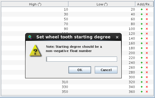
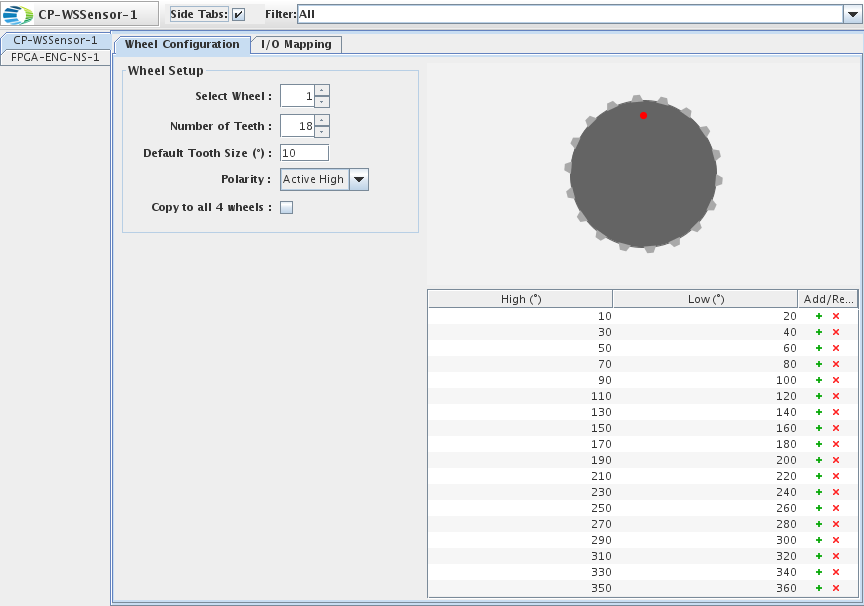
 and
and  buttons to
customize the wheel teeth. However, note that using these buttons results in values of the Number of Teeth
and Default Tooth Size fields being inapplicable.


