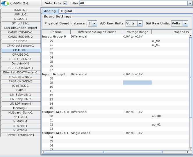
The CP-MFIO is a multi-function card manufactured by Concurrent. It provides 16 analog inputs, 16 analog outputs, and 96 digital input/output channels.
CP-MFIO
WC-CP-FIO (v 23.0.5)
ICS-SWB-1278
Mappings for the analog channels
Select the physical board that this panel instance will use.
The CP-MFIO board has multiple functionalities - multi-function I/O or FPGA engine sensor simulation - determined by the firmware
installed on the board.
The same low level Linux driver is used by all the functionality. A system can have both type of board installed so in this case it is necessary to tell the
driver which physical instance of the board to use for the specific SimWB panel. The instances of the boards know to the driver can be listed with the shell command cat /proc/ccurpfmc
Selects the units of raw values of Analog Input signals as being either Count or Volt. This is the unit used to store the raw value in the SimWB RTDB for the mapped item.
When Volt is selected, the voltage read from the board is stored as the raw value in the RTDB. If your I/O point is defined with an associated engineering conversion, you must write the conversion to convert from volt to engineering unit. Without engineering conversion, the item value and raw value in the RTDB will be the same and expressed in volts.
When Count is selected, the unsigned 15-bit integer value read from the board is stored as the raw value. If your I/O point is defined with an associated engineering conversion, you must take into account that the raw value range of 0 to 0x7fff corresponds to the voltage range configured on the board.
Same as A/D Raw Unit, except in the context of Analog Output signals.
Analog channels that I/O points may be mapped to. Note that there are separate input and output channels indented under the appropriate label.
The output channels can be configured in differential or single ended mode in group of four. When differential mode is selected, only the even channels can be mapped. I.E., when differential mode is selected, the number of channels available per group is reduced from 4 to 2.
Selects the voltage range for all the channels in a given input/output group.
To change the voltage range of a group, click on the table cell with the current voltage range and use the drop-down menu to select the desired voltage range.
Points the channel is mapped to.
Select a channel on the left side of the I/O Mappings form, then click on a check box for an I/O point on the right side of the form. See I/O Mappings... for details.
Mappings for the digital channels/bits. 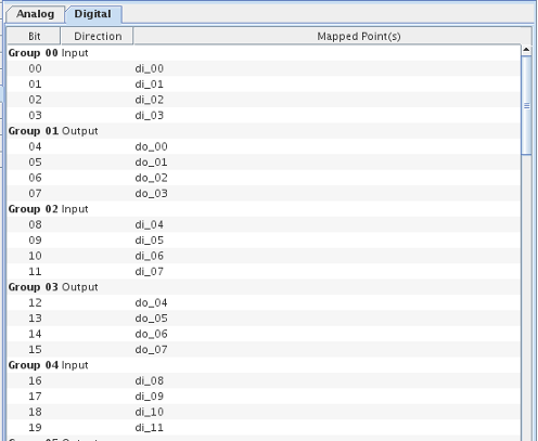
Digital channels that I/O points may be mapped to. The digital channels are grouped into 24 ports of 4 channels. The I/O direction of the ports is selectable.
Shows the I/O direction of the ports and selects the direction of the ports.
To change the I/O direction of a port, click on the table cell with the current direction and select a new direction from the drop down menu. If the I/O direction is changed, any I/O point mappings to any of the four digital channels on that port are removed.
Points the channel is mapped to.
Select a bit on the left side of the I/O Mappings form, then click on a check box for an I/O point on the right side of the form. See I/O Mappings... for details.
The CP-MFIO card has four connectors. The following are the pinouts for each connector, as seen when the card is plugged into the machine.
Top Left (DIOs 64-95) 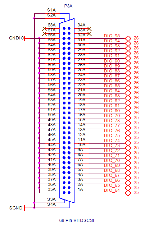 |
Top Right (AIs 00-15 and AOs 00-15) 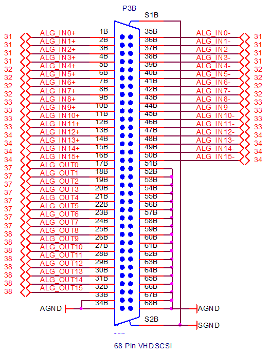 |
Bottom Left (DIOs 32-63) 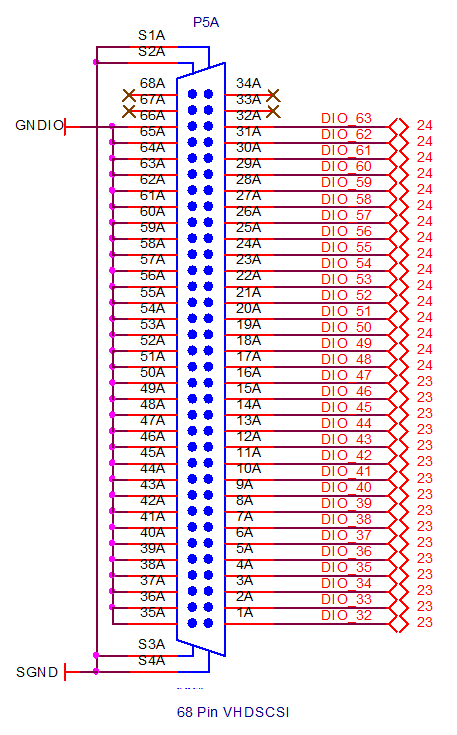 |
Bottom Right (DIOs 00-31) 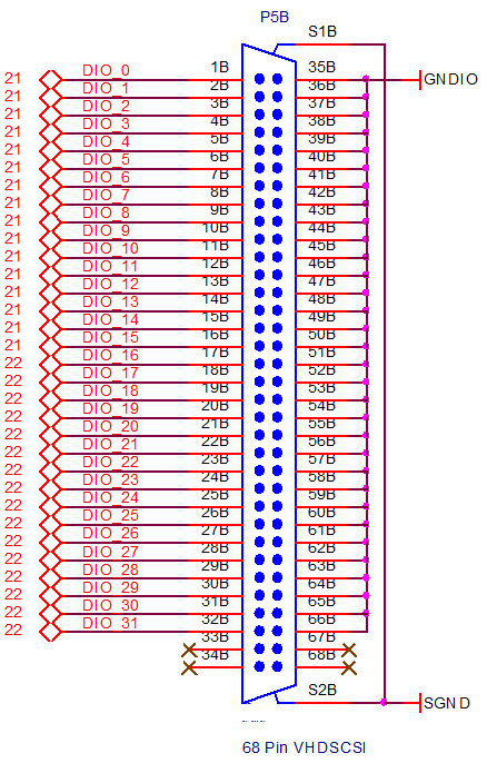 |