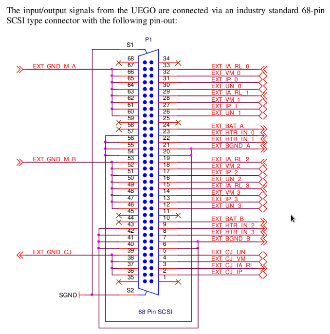
For each channel, you can map:
- Lambda - Calculated stoichiometric ratio of the air / fuel mixture in the exhaust gases.
- Cell Temp (°C) - Calculated cell temperature of the probe, specified in degree Celsius.
- Heater Input - Duty cycle of the power applied to the heater, specified in the [0 100] range.
- Faults - You can apply the following faults to the UN (Nernst cell voltage), VM (virtual ground), IP (primary pumping current), and IA/RL (trim resistor) lines. Only one fault can be active at a given frame.
- Open: When the associated DO variable is high, the relevant line is open.
- Ground: When the associated DO variable is high, the relevant line is grounded.
- Vbat: When the associated DO variable is high, the relevant line is connected to Vbat.
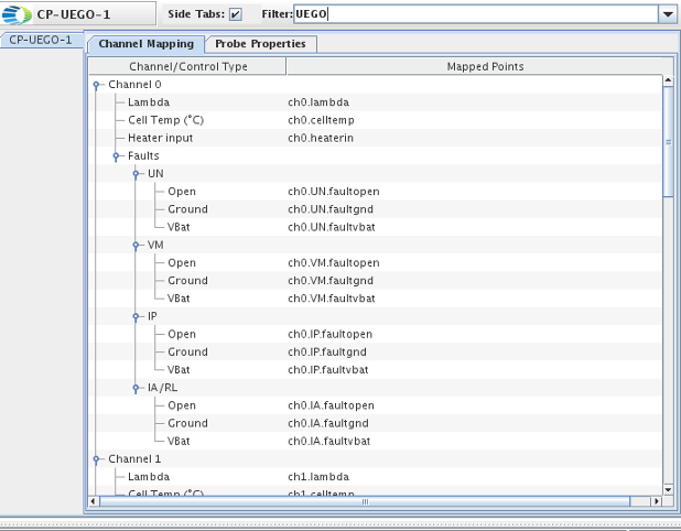
The Probe Properties pane allows you to configure each channel of the UEGO sensor.
- Channel: Select the channel to configure.
- Narrow band:
Specify whether the card should be used in:
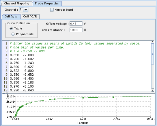
- Wide band mode - Cell voltage is equal to the product of cell resistance and Ip, expressed in mA. The following curve definitions are required in this mode:
- Cell λ/Ip
- Curve definition:
Specify mechanism used to define the λ/Ip curve in the editor below.
- Table - Enter the (λ, Ip) value pairs, one per line, using a space delimiter.
- Polynomials - Enter the curve polynomials, one per line, using the following convention (polynomial order must be four or less):
[λmin λmax] a0 a1 a2 a3 a4Such that the curve is represented by: a4λ4 + a3λ3 +a2λ2 +a1λ1 +a0
For a piecewise function, enter one line per polynomial. For example, suppose the function is represented by c1 and c2. You must enter:
[λmin,c1 λmax,c1] a0,c1 a1,c1 a2,c1 a3,c1 a4,c1[λmin,c2 λmax,c2] a0,c2 a1,c2 a2,c2 a3,c2 a4,c2To ensure contiguity, λmax,c1 must equal λmin,c2.
- Offset voltage: Voltage offset. This is the default cell voltage when λ == 1.
- Cell resistance: Cell resistance used to calculate cell voltage.
- Curve definition:
Specify mechanism used to define the λ/Ip curve in the editor below.
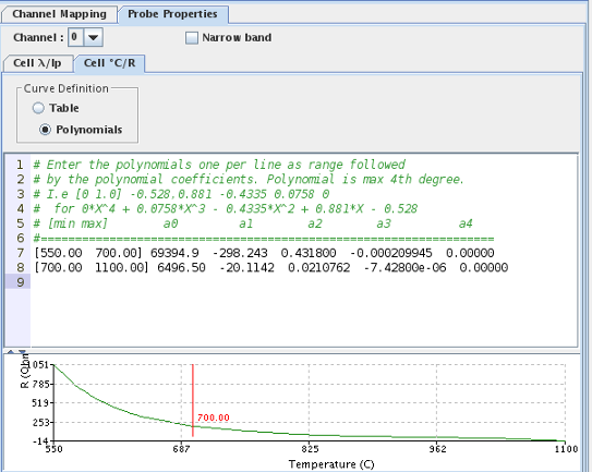
- Cell °C/R
This curve defines the relationship between the probe resistance and its temperature. To define this curve, use the curve definition mechanism described for the Cell λ/Ip curve.
- Cell λ/Ip
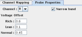
- Narrow band mode - Specify the voltages for rich,normal and lean mixtures.
- Rich : if λ <= 0.99
- Lean : if λ >= 1.01
- Normal : otherwise
- Wide band mode - Cell voltage is equal to the product of cell resistance and Ip, expressed in mA. The following curve definitions are required in this mode:
 |
 |
