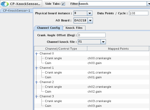
Configure board settings.
- Physical Board Instance: Select the physical board instance that this panel will use. Default value is 0.
- Data Points / Cycle: Number of data points output for each channel, per cycle. Default value is 108.
- AO Board: Select the output board associated with the knock sensor. Options are 16AO16 and DA3218. Default value is DA3218.

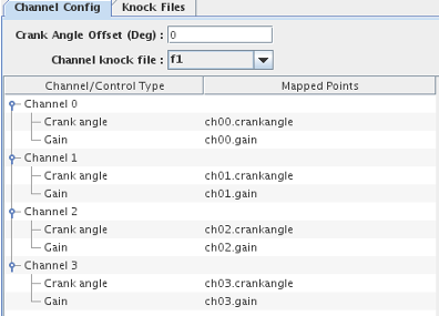
The Channel Config pane allows you to individually configure each channel of the specified output card. To configure a given channel, click on the relevant node in the table. For example, to configure channel 0, click the "Channel 0" line in the table. For each channel you can specify:
- Channel Angle Offset (Deg): Offset applied to engine crank angle at each frame, specified as a float (unit is degrees).
- Channel Knock File: Name of the ASCII file that specifies the 1-d lookup table applicable to the channel. The file must have the extension ".knock". For more information on how to create these files, see Creating a Knock File.
I/O Mapping:
For each channel, you can map:
- Crank angle - Engine crank angle, specified in the [0 θmax]° range. θmax is defined in the meta-data line of the relevant knock file.
- Gain - Scaling factor applied to output signal. If the resulting value exceeds the supported voltage for the card, then the I/O tasks uses the maximum output voltage. Similarly, for resulting voltages that are lower than the minimum supported voltage, the I/O task uses the minimum supported voltage instead.

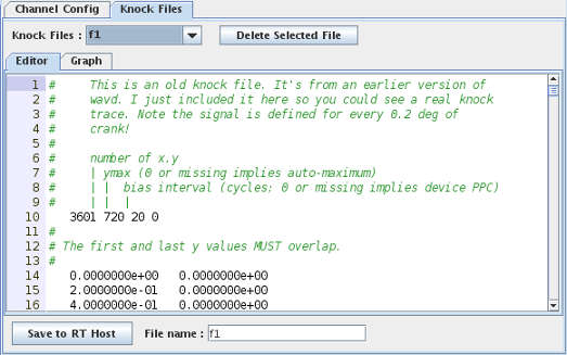
- Knock Files: List of all knock files specified for the RTDB. Such files have a ".knock" extension.
- Delete Selected File: Click this button to delete the knock file selected in the Knock Files dropdown list.
- Editor: Use this editor to create a knock file. For more information, see Creating a Knock File.
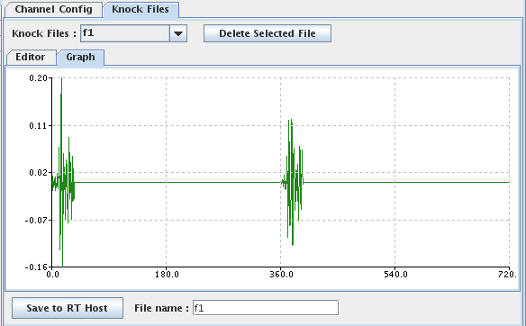
- Graph: Displays a graphical representation of the signal specified by the knock file. You can zoom in and out of the graph by using the mouse wheel. You can pan the graph display by clicking and dragging the mouse.
- Save to RT Host: Click this button to create a knock file for the RTDB. Specify the knock file name in the File name field.
Creating a Knock File:
A knock file is an ASCII file with a ".knock" extension that specifies an output waveform for a given angle. To create a knock file:
- Load the RTDB of interest. This step is important because the ".knock" file must reside in the relevant RTDB folder.
- In the Editor pane, enter:
- Comments regarding the signal. Comment lines start with the "#" symbol.
- Metadata regarding the signal. Must be the first non-comment line in the file and include only the following four entries:
num_points_defined θmax gain bias
Here:
num_points_defined- Number of (angle,output value) data points defined in the file.θmax- Maximum angle before the wave repeats.gainbias- Gain and bias are used together to apply a one-time transformation of the output data as it is read in. If you want the data to be used as-is, make these 1.0 and 0.0.
- Angle/Output value data pairs, delimited by a space.
θ y
Here:
θ- Angle, specified in degrees.output- Output voltage value, specified in Volts.
- Enter the name for the knock file in the File name field and then click Save to RT Host. The knock file is placed in the folder for the loaded RTDB.
The following are example knock files for the "knock" RTDB that is shipped in the Hardware-Tests/Knock-sensor project:
/usr/local/ccursim/projects/__project.Hardware-Tests/__project.Knock-sensor/RTDB/knock/f1.knock/usr/local/ccursim/projects/__project.Hardware-Tests/__project.Knock-sensor/RTDB/knock/f2.knock
 |
 |