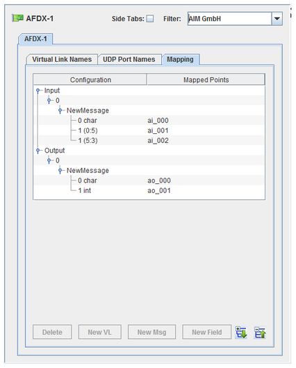
For the AFDX board, I/O points are mapped to fields within a message and messages are associated with virtual links which are deterministic ethernet frames encapsulating the messages and additional information.

CS-AM-API-FDX-2.
WCS-AM-API-FDX.
ICS-SWB-1210.

Expands the hierarchy tree showing board configuration.

Collapses the hierarchy tree showing the board configuration to show only the channel nodes.

Adds a virtual link for the selected I/O direction.

Adds a message definition to the selected virtual link.

Adds a field to the selected message.

Deletes the selected node and everything, including mappings, below it. The top level nodes cannot be deleted.
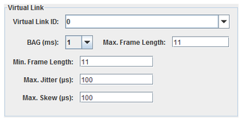
Identifier of the virtual link. A number between 0 and 65535 inclusive may be typed in or a named virtual link may selected from the pull down list. See Virtual Link Names for instructions on how to set up names for virtual links.
Bandwidth Allocation Gap. This value determines the latency of received messages.
Maximum length in bytes of the frame that will be received on this virtual link ID
Length of smallest frame, in bytes, expected to be received on this virtual link.
Maximum amount of jitter, in microseconds that are expected between reception of redundant frames on ports A and B.
Maximum delay, in microseconds, that should be acceptable between reception of redundant frames on ports A and B before declaring an error.
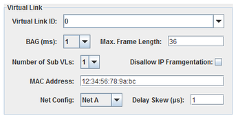
Identifier of the virtual link. A number between 0 and 65535 inclusive may be typed in or a named virtual link may selected from the pull down list. See Virtual Link Names for instructions on how to set up names for virtual links.
Bandwidth Allocation Gap. This value determines how fast you can send transmit messages. The sampling rate specified for messages must be compatible with this setting.
Maximum length in bytes of the frame that will be sent on this virtual link ID
The maximum number of sub virtual links (1 to 4) that will be sent under this virtual link.
When set ; do not allow the message to be larger than the maximum frame set for the virtual link.
The MAC address must be a valid AFDX MAC address. I.e. in the form 02:00:XX:XX:XX:XX
Only sent frames on port A.
Only send frames on Port B.
Send frames on both ports A and B with no delay.
Send frames on both ports A and B, but delay the transmission on port A by the delay skew.
Send frames on both ports A and B, but deley the transmission on port B by the delay skew.
Delay in microseconds between frames sent on ports A and B when either Delay A or Delay B is selected.
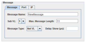
Unique name for this message.
Sub-virtual link number. A virtual link may have up to four messages associated with it. Each must have a unique sub-virtual link number.
Maximum length of the message in bytes. This does not include the virtual link frame header and should be smaller than the maximum frame length defined for the virtual link.
(For output messages only)
Only sent frames on port A.
Only send frames on Port B.
Send frames on both ports A and B with no delay.
Send frames on both ports A and B, but delay the transmission on port A by the delay skew.
Send frames on both ports A and B, but deley the transmission on port B by the delay skew.
Delay in microseconds between rames sent on ports A and B when either Delay A or Delay B is selected.
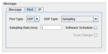
Service Access Point..
UDP.
UDP, I.e. not SAP.
This is the FIFO transmission mode in SimWB terminology.
When selected, the message is transmitted repeatedly at a specufied rate.
Period, in milliseconds, at which the transmit message will be sent. (UDP Sampling only). The board will send the message at this rate regardless of data values. This rate must be compatible with the BAG defined for the virtual link.
The message can be scheduled for repeated transmission either by the firmware or SimWB. Software schedule means SimWB will schedule repeated transmission of the message.
When a message transmission is scheduled by the hardware, its transmission rate cannot be controlled by SimWB via the API.
When the message transmission is FIFO, SimWB will either send the message whenever its payload content changed (TX on change) or only upon user request via an API call.
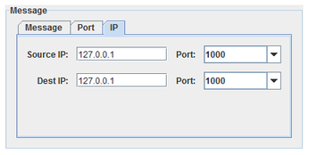
Source and Destination IP addresses and ports. Ports numbers may be typed in or named ports may be selected from the list in the drop-down combo box.
A valid AFDX address must be specified. I.e. as 10.X.Y.Z where X < 31.
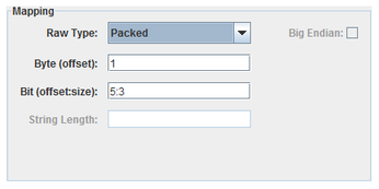
I/O points are mapped to specific fields of messages. Single-bit Packed fields can only be mapped to digital points. All other fields can only be mapped to analog points.
Specifies how to interpret the raw bits of the message field.
Integer bit field, specified with a byte offset to a 32-bit integer and a bit offset and size within that 32-bit field. Single bit fields are mapped to digital points, all others to analog points.
One-byte integer field, specified with a byte offset. Integer fields are mapped to analog points.
Two-byte integer field, specified with a byte offset. Integer fields are mapped to analog points.
Four-byte integer field, specified with a byte offset. Integer fields are mapped to analog points.
Four-byte floating point field, specified with a byte offset. Floating-point fields are mapped to analog points.
Null-byte terminated string, specified with a byte offset. String fields are mapped to string points.
Fied length string, specified with a byte offset and a string length. String fields are mapped to string points.
Field’s offset in the message in bytes. For Packed, this is the offset of the 4-byte integer containing a bit field.
Bit offset and size of a Packed field within a 4-byte integer block. Bits are numbered from the high order bit of the 4-byte block. Which byte this bit is in is determined by the Big Endian setting. The offset is measured from the high order bit of the block to the high order bit of the field.
Length of a fixed length string field.
Interprets values as most significant byte first. This is the reverse of the default way data is handled on Intel x86 platforms.
Configuration tree.
I/O point(s) a field is mapped to.
To map a field to a channel, select a field on the left side of the I/O Mappings form, then click on a check box for an I/O point on the right side of the form. See I/O Mappings... for details.
Names may be assigned to virtual link numbers for the user’s convenience. Entries in this table are available in pull-down combo boxes in the AFDX configuration dialog.
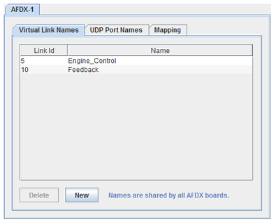
Link ID number. Edit the number in-place in the table by double clicking on the table cell.
Convenient name for the Link ID. Edit the name in-place in the table by double clicking on the table cell.

Deletes the selected virtual link name. This does not effect the configuration of the AFDX boards. Only the convenient name for the virtual link is removed. No virtual links configured on AFDX boards are modified or deleted.

Creates a new name for a virtual link. The new entry is of the next unnamed virtual link and is given a default unique name. Double click on the entries cells in the table to edit these default values.
Names may be assigned to UDP port numbers for the user’s convenience. Entries in this table are available in pull-down combo boxes in the AFDX configuration dialog.
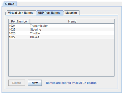
UDP port number. Edit the number in-place in the table by double clicking on the table cell.
Convenient name for the UDP port. Edit the name in-place in the table by double clicking on the table cell.

Deletes the selected UDP port name. This does not effect the configuration of the AFDX boards. Only the convenient name for the UDP port is removed. No UDP ports configured on AFDX boards are modified or deleted.

Creates a new name for a UDP port. The new entry is of the next unnamed UPD port, starting at 1024, and is given a default unique name. Double click on the entries cells in the table to edit these default values.
This I/O task packs all AFDX raw output messages corresponding to the AFDX output items and places them into the AFDX output FIFO queue. The process will not queue a request into the FIFO queue if the raw AFD message is unchanged since the last test cycle.
The queue is read by the afdxasyncio asynchronous task that writes them to the hardware board.
This process runs asynchronous to the simulation loop and handles both inputs from and outputs to the AFDX boards. Due to the fact that an AFDX board can only be opened by one task at a time and a single board can be configured to do inputs and outputs simultaneously, this process is multithreaded.
There is a separate thread for each board that is configured as input (that is, at least one channel on the board is configured for input and at least one RTDB variable is mapped to that channel).
There is a single thread for processing outputs to all boards that are configured as output (that is, at least one channel on the board is configured for output and at least one RTDB variable is mapped to that channel.) The output thread polls the AFDX output FIFO at a regular interval. The default interval is every 5 milliseconds and can be specified as a command line argument with –t msec in the options column of the I/O Tasks form

|
ADLINK 7296 | AI64LL |

|