 |
|
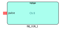
The INJ_IGN block captures injection or ignition pulses coming from the ECU. The information captured is relative to the TDC of the cylinder for which the cannel is configured. The block can handle both injection and ignition digital inputs. The CRANK_CAM block is a prerequisite for using the INJ_IGN block.
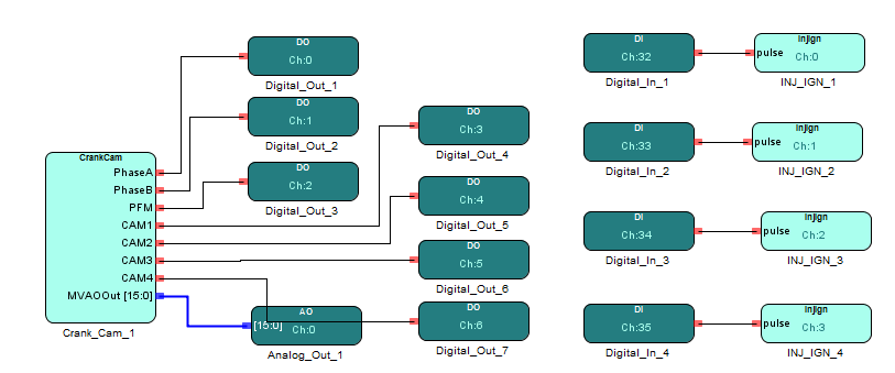
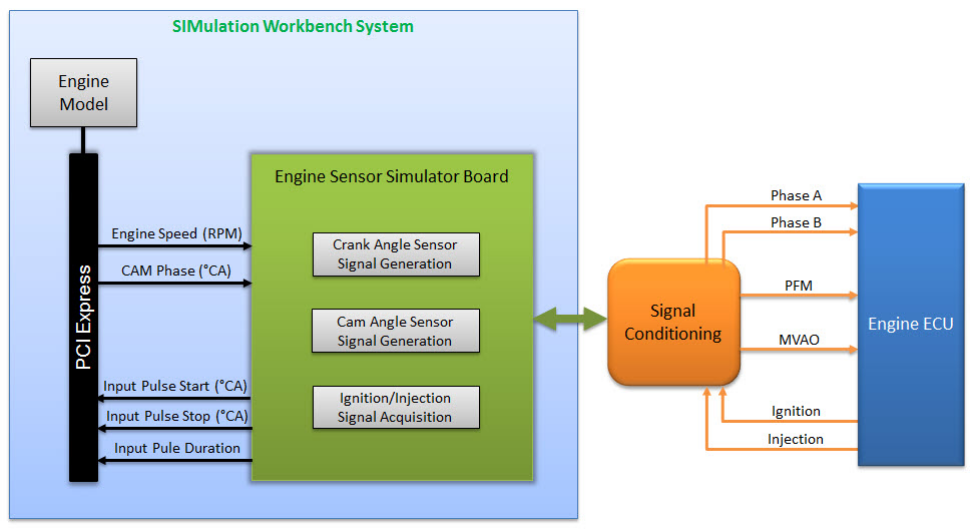
Figure below shows an example usage of the CRANK_CAM and INJ_IGN IP core blocks. A Simulink/Custom C model sends the RPM value to the IP core and the different waveforms are generated for the ECU based on the Crank and Cam tooth profiles. Injection and Ignition inputs are capture in relation to the crank angle and then presented it back the engine model.
The Ignition Injection block inputs are connected to their respective Crank Cam block outputs. This ensures that the entire system works as expected.