 |
|
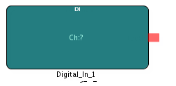
The Digital Input IP block enables you to connect to one or more of the 96 digital input channels on the board. The digital lines are are grouped into banks for 4. Individual banks can be controlled to be either digital input or digital output.
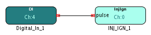
The digital input coming into channel 4 is connected to the INJ_IGN block which captures information about the injection and ignition pulses.
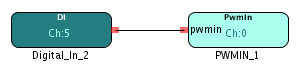
The digital input coming into channel 5 is connected to the PWM_IN block which calculates the frequency and duty cycle of the input signal.
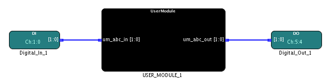
The Digital Input block gets inputs from 2 channels, channel 0 and channel 1 and outputs it to the User Module block. The User Module block creates a multi-bit output which is then sent to 2 digital output channels, channel 4 and channel 5 with the Digital Output block. This example demonstrates the use of multiple channels from a single Digital block.