Block Info
- Version: 1.0
First Release: FPGAWB 2018.1-0
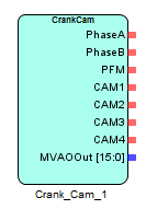
The CRANK_CAM block is the primary block which provides the combustion engine sensor simulator functionalities listed below:
- Generation of crank-angle sensor signal
- Arbitrary pulse pattern configuration with less than 0.006° CA resolution at ±30,000RPM
- Waveform generation identifiable by crank reverse rotation
- Phase shifting output (A/B-Phase)
- Multi-level voltage output
- Programmable frequency modulation (PFM) output
- Generation of cam-angle sensor signals
- Waveforms up to 4 cam-shafts
- Arbitrary pulse pattern configuration with less than 0.006° CA resolution at ±30,000RPM for each shaft
- Synchronization with crank-angle
- Individual phase variable (advance/delay) command for individual shaft (resolution 0.01°CA)
Figure below shows an example usage of the CRANK_CAM IP core block. A Simulink/Custom C model sends the RPM value to the IP core and the different waveforms are generated for the ECU based on the Crank and Cam tooth profiles. Only one instance of this block is allowed in a FPGAWB project.
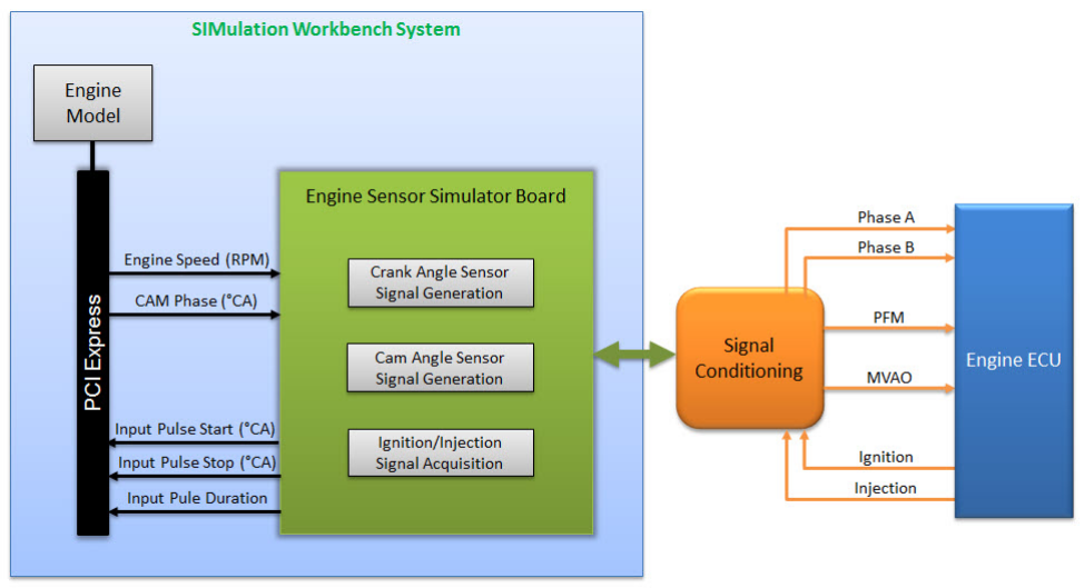
Figure: Application example
Examples
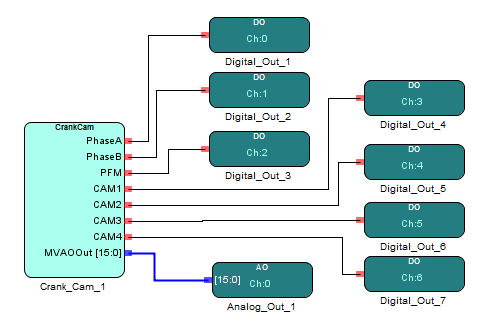
Example 1
The digital outputs from the CRANK_CAM block are connected to digital output blocks and the MVAO and Crank Angle are connected to analog output blocks.