 |
|
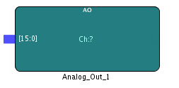
The Analog Output IP block enables you to connect to one of the 16, 16 bit analog output channels on the board. The board supports both single ended and differential outputs. The outputs can be software configured as 16-channel single-ended outputs, 8-channel differential outputs, or a combination of single-ended and differential on a per-DAC granularity. The DACs are arranged and controlled in banks of 4. The driver or application software sets the DAC data format and the DAC voltage range.
DAC to channel association is a follows:
If you plan to use differential analog output, only connect to the even number analog output channel and use the driver API to configure the DAC channel to be differential.
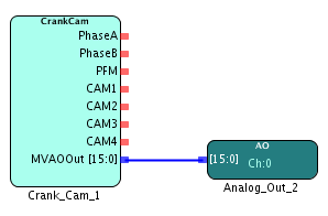
Multi-voltage analog output from the CRANK_CAM block is connected to analog output pin 0.
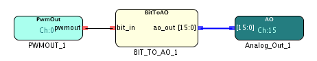
Digital output from the PWM_OUTPUT block is scaled and converted to a two level multi-bit value using the BIT_TO_AO block and then passed on to the analog output pin 15. A 0 coming from the PWM_OUTPUT block is converted to -5V on the analog channel and a 1 coming from the PWM_OUTPUT block is converted to a +5V signal.