 |
|
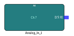
The Analog Input IP block enables you to connect to one of the 16, 16 bit analog input channels on the board. The board supports both single ended and differential inputs. The ADCs are arranged and controlled in banks of 8. The driver or application software sets the ADC data format and the ADC voltage range.
ADC to channel association is a follows:
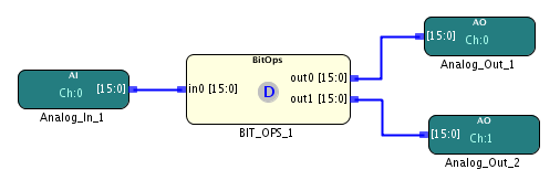
The analog input waveform coming into analog input channel 0 is duplicated using the BIT_OPS block and then the output is sent to analog output channel 0 and channel 1.
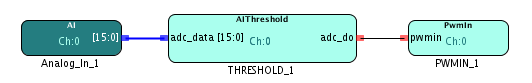
Thresholding is applied to the analog input comming in on channel 0 to convert it into a digital signal. This digital signal is then passed onto the PWM_INPUT channel 0 to measure the frequency and the duty cycle.