Specifies which hardware an I/O point reads its value from or writes it to during stages 1 and 4, respectively, of the test cycle. There are two kinds of devices that can be mapped to I/O points (plus a few outliers that don’t quite fit either category). Channel-based devices have individually named channels that can read or write a single value. Message-based devices read and write multi-byte messages, and I/O points are mapped to specific fields within those messages. This section will not document all the details of the various devices. See Configuring I/O Devices for details on individual boards. This section documents the general principles that apply to most of them.
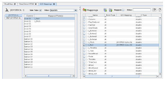
The I/O Mappings form is divided into two panes. The left pane allows the user to select and configure I/O devices and to select the channels or fields of those devices to be mapped to I/O points. The right pane usually provides a list of appropriate I/O points for mapping channels or fields to. See the documentation on specific devices for details about any exceptions to this.
The vertical divider bar between the panes may be dragged to the left or right to resize them. There are little arrow buttons on the divider bar near the top for making one pane or the other instantly resize to take up the whole form or to restore the panes to their original sizes.
See Configuring I/O Devices for details on specific channel-based devices.
Displays the I/O device tabs on the left side of the tabbed pane instead of at the top. This is very useful when there are lots of devices configured on a system as it allows more tabs to be seen at one time.
Selects a subset of the I/O devices to display in the tabbed pane from the drop down menu, or from the typed-in a regular expression which restricts the list of devices to those whose name matches the regular expression. See Regular Expressions.
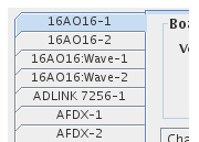
Each I/O device configured on the real-time host (see I/O Devices...) has a tab in the tabbed pane. Use the Side Tabs option to display the tab labels on the left edge of the pane instead of at the top to see more tabs when many devices are configured on the real-time host. Use the Filter to display a subset of the I/O devices tabs.
The contents of the tab divide into three sections from top to bottom:
If there are any options that apply to the whole I/O device instead of just to a single channel, they are displayed above the channel table.
The channel table is always displayed. Each row shows the name of the channel and any I/O points that channel is mapped to. Click on a row to select a channel. The pane to the right will display a list of I/O points that may be mapped to the selected channel, and the channel options below the table (if there are any) can be used to set options on the selected channel.
If there are any options that can be set on individual channels, they are displayed below the channel table when a channel is selected. Select a channel in the channel table, then make changes in the channel options below. Sometimes, if there are only a small number of options, the channel options will be in columns in the channel table itself.
See Configuring I/O Devices for details on specific message-based devices.

Displays the I/O device tabs on the left side of the tabbed pane instead of at the top. This is very useful when there are lots of devices configured on a system as it allows more tabs to be seen at one time.
Selects a subset of the I/O devices to display in the tabbed pane from the drop down menu, or from the typed-in a regular expression which restricts the list of devices to those whose name matches the regular expression. See Regular Expressions.
Each I/O device configured on the real-time host (see I/O Devices...) has a tab in the tabbed pane. Use the Side Tabs option to display the tab labels on the left edge of the pane instead of at the top to see more tabs when many devices are configured on the real-time host. Use the Filter to display a subset of the I/O devices tabs.
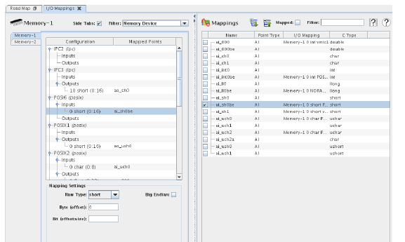
Message-based devices are configured via a hierarchy of settings presented as a tree much like the tree for hierarchical point names. Below the table are any settings specific to the node of the tree that is selected in the table.
For example, if the vmic1 node is selected above, settings appear below the table that allow reconfiguring the vmic1 region. It can be renamed, assigned to a different memory board, etc. There are no settings for the Inputs and Outputs nodes, but selecting the field nodes allows one to change the type and bits of the selected field.
Below the node settings are buttons for manipulating the tree.

Deletes the selected node in the tree. Any points mapped to any field descended from that node will be unmapped from the deleted fields.
Creates a new node in the tree. There will be a New button for each node type. The New buttons will be disabled unless an appropriate parent or sibling node is selected. This is explained in detail below on the New Field button.

Creates a new field. All message-based devices have fields. If an existing field is selected, the new field will be in the same message as the selected field. If a message is selected, the new field will be in that selected message. All the New ... buttons work similarly with sibling and parent nodes.
In the above screen shot, the New Field button will be enabled if a field is selected or if an Inputs or Outputs node is selected. If a root memory region node is selected, New Field is not enabled since no message the field can belong to is apparent.
New Region is always enabled since regions are the root nodes. It is always apparent where they belong.
Fields must be mapped to analog points unless their size is one bit, in which case they must be mapped to digital points. The right hand pane will show only the appropriate points for the selected field.

Expands the hierarchy tree of device configurations.

Collapses the hierarchy tree of device configurations.
Some boards may have a different form on the right hand pane. See individual board documentation in Configuring I/O Devices for details.
Expands the hierarchy tree for all point names in the point table. Point names with periods in the names are hierarchical names and are displayed as a tree. A.ai000 and A.ai001 would display ai000 and ai001 as children of the A node.
Collapses the hierarchy tree for all point names in the point table to show just the top level nodes.
Displays in the points table only I/O points mapped to the selected hardware channel or message field.
Displays in the points table only I/O points whose name matches the regular expression. See Regular Expressions.

Opens a short video clip that demonstrates the basic workflow of this form.

Opens this section of the manual.
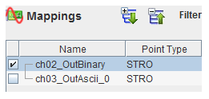
Displays and changes mappings between the selected channel or message field and I/O points. Each I/O point has a check box next to it. When a channel or message field is selected in the left hand pane, the Points Table will be populated with points that can be mapped to that selected entity. If the channel or field is already mapped to one or more points, the check box next to those point will be checked and the points’ rows will be highlighted. When no channel or field is selected in the left hand pane, a brief help message is displayed in place of the points table in the right hand pane.
To map a point to a channel or message field selected in the left hand pane, click on the check box next to the point in the right hand pane. Alternatively, double click on the point’s row to map the point to the selected channel or message field. For channel boards, double clicking will also advance the selected channel to the next channel.
Multiple input points can be mapped to a single input channel or message field, but an input point can only be mapped to a single input channel or field. If a point is already mapped to a input channel or field when its check box is checked, that point’s previous mapping will be replaced.
An output point can be mapped to multiple output channels or fields, but an output channel or message field can only be mapped to a single output point. If the selected channel or message field is already mapped to an output point when a check box is checked, that channel or field’s previous mapping will be replaced.

Commits all pending edits to the real-time host. See Apply .

Discards all pending edits.

|
Engineering Units Conversions... |